Datasheet 搜索 > 微控制器 > Microchip(微芯) > PIC16C745-I/SO 数据手册 > PIC16C745-I/SO 数据手册 54/166 页
 器件3D模型
¥ 31.942
PIC16C745-I/SO 数据手册 - Microchip(微芯)
制造商:
Microchip(微芯)
分类:
微控制器
封装:
SOIC-28
描述:
MICROCHIP PIC16C745-I/SO 微控制器, 8位, 一次性可编程, PIC16C7xx, 24 MHz, 14 KB, 256 Byte, 28 引脚, SOIC
Pictures:
3D模型
符号图
焊盘图
引脚图
产品图
页面导航:
引脚图在P1P11P12P53P54Hot
原理图在P10P31P33P35P37P38P40P43P46P49P53P54
标记信息在P147P148
封装信息在P73P147P149P150P151P152P153P154P155
功能描述在P2P5
技术参数、封装参数在P103P112P132P133P143
应用领域在P58P66
电气规格在P103
导航目录
PIC16C745-I/SO数据手册
Page:
of 166 Go
若手册格式错乱,请下载阅览PDF原文件
PIC16C745/765
DS41124D-page 54 Preliminary 1999-2013 Microchip Technology Inc.
9.2 Compare Mode
In Compare mode, the 16-bit CCPR1 register value is
constantly compared against the TMR1 register pair
value. When a match occurs, the RC2/CCP1 pin is:
• Driven high
•Driven low
• Remains unchanged
The action on the pin is based on the value of control
bits CCP1M<3:0> (CCP1CON<3:0>). At the same
time, interrupt flag bit CCP1IF is set.
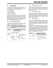
FIGURE 9-2: COMPARE MODE OPERATION
BLOCK DIAGRAM
9.2.1 CCP PIN CONFIGURATION
The user must configure the RC2/CCP1 pin as an out-
put by clearing the TRISC<2> bit.
9.2.2 TIMER1 MODE SELECTION
Timer1 must be running in Timer mode or Synchro-
nized Counter mode if the CCP module is using the
compare feature. In Asynchronous Counter mode, the
compare operation may not work.
9.2.3 SOFTWARE INTERRUPT MODE
When Generate Software Interrupt mode is chosen, the
CCP1 pin is not affected. The CCPIF bit is set causing
a CCP interrupt (if enabled).
9.2.4 SPECIAL EVENT TRIGGER
In this mode, an internal hardware trigger is generated,
which may be used to initiate an action.
The special event trigger output of CCP1 resets the TMR1
register pair. This allows the CCPR1 register to effectively
be a 16-bit programmable period register for Timer1.
The special event trigger output of CCP2 starts an A/D
conversion (if the A/D module is on) and resets the
TMR1 register pair and starts an A/D conversion (if the
A/D module is enabled).
9.3 PWM Mode (PWM)
In pulse width modulation mode, the CCPx pin pro-
duces up to a 10-bit resolution PWM output. Since the
CCP1 pin is multiplexed with the PORTC data latch, the
TRISC<2> bit must be cleared to make the CCP1 pin
an output.
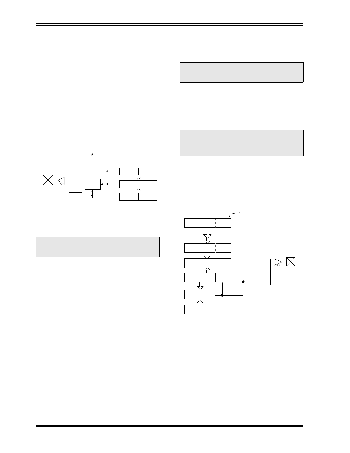
Figure 9-3 shows a simplified block diagram of the CCP
module in PWM mode.
For a step by step procedure on how to set up the CCP
module for PWM operation, see Section 9.3.3.
FIGURE 9-3: SIMPLIFIED PWM BLOCK
DIAGRAM
A PWM output (Figure 9-4) has a time base (period) and
a time that the output stays high (duty cycle). The fre-
quency of the PWM is the inverse of the period (1/period).
Note: Clearing the CCP1CON register will force
the RC2/CCP1 compare output latch to the
default low level. This is not the data latch.
CCPR1H CCPR1L
TMR1H TMR1L
Comparator
QS
R
Output
Logic
Special Event Trigger
Set flag bit CCP1IF
(PIR1<2>)
match
RC2/CCP1
TRISC<2>
CCP1CON<3:0>
Mode Select
Output Enable
Pin
Special event trigger will:
reset Timer1, but not set interrupt flag bit TMR1IF (PIR1<0>),
and set bit GO/DONE
(ADCON0<2>).
Note: The special event trigger from the
CCP1and CCP2 modules will not set inter-
rupt flag bit TMR1IF (PIR1<0>).
Note: Clearing the CCP1CON register will force
the CCP1 PWM output latch to the default
low level. This is not the PORTC I/O data
latch.
CCPR1L
CCPR1H (Slave)
Comparator
TMR2
Comparator
PR2
(Note 1)
R
Q
S
Duty Cycle Registers
CCP1CON<5:4>
Clear Timer,
CCP1 pin and
latch D.C.
TRISC
<2>
RC2/CCP1
Note 1: 8-bit timer is concatenated with 2-bit internal Q clock
or 2 bits of the prescaler to create 10-bit time base.
器件 Datasheet 文档搜索
AiEMA 数据库涵盖高达 72,405,303 个元件的数据手册,每天更新 5,000 多个 PDF 文件
