Datasheet 搜索 > Microchip(微芯) > PIC16F1823T-E/ST 数据手册 > PIC16F1823T-E/ST 数据手册 133/398 页

 器件3D模型
¥ 6.131
PIC16F1823T-E/ST 数据手册 - Microchip(微芯)
制造商:
Microchip(微芯)
封装:
TSSOP
描述:
8月14日引脚闪存单片机采用nanoWatt XLP技术 8/14-Pin Flash Microcontrollers with nanoWatt XLP Technology
Pictures:
3D模型
符号图
焊盘图
引脚图
产品图
页面导航:
引脚图在P13P14P15P16P17P127P200P202P209P316Hot
典型应用电路图在P317
原理图在P12P20P55P66P75P99P127P131P133P149P154P160
封装尺寸在P373
标记信息在P371P372
封装信息在P371P382
功能描述在P307
技术参数、封装参数在P57P61P87P104P131P134P144P147P163P164P170P259
应用领域在P53P57P58P211P217
电气规格在P57P61P87P131P134P144P147P163P164P170P310
导航目录
PIC16F1823T-E/ST数据手册
Page:
of 398 Go
若手册格式错乱,请下载阅览PDF原文件
2010 Microchip Technology Inc. Preliminary DS41413A-page 133
PIC12F/LF1822/16F/LF1823
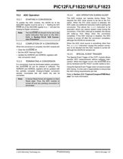
15.0 ANALOG-TO-DIGITAL
CONVERTER (ADC) MODULE
The Analog-to-Digital Converter (ADC) allows
conversion of an analog input signal to a 10-bit binary
representation of that signal. This device uses analog
inputs, which are multiplexed into a single sample and
hold circuit. The output of the sample and hold is
connected to the input of the converter. The converter
generates a 10-bit binary result via successive
approximation and stores the conversion result into the
ADC result registers (ADRESH:ADRESL register pair).
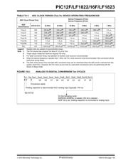
Figure 15-1 shows the block diagram of the ADC.
The ADC voltage reference is software selectable to be
either internally generated or externally supplied.
The ADC can generate an interrupt upon completion of
a conversion. This interrupt can be used to wake-up the
device from Sleep.
FIGURE 15-1: ADC BLOCK DIAGRAM
Note 1: When ADON = 0, all multiplexer inputs are disconnected.
2: Not available on PIC12F/LF1822.
DAC
VDD
VREF+
ADPREF = 10
ADPREF = 00
ADPREF = 11
FVR Buffer1
ADON
(1)
GO/DONE
VSS
ADC
00000
00001
00010
00011
00100
00101
00111
00110
11110
CHS<4:0>
AN0
AN1
AN2
AN4
(2)
AN5
(2)
AN6
(2)
AN7
(2)
AN3
11111
ADRESH ADRESL
10
16
ADFM
0 = Left Justify
1 = Right Justify
器件 Datasheet 文档搜索
AiEMA 数据库涵盖高达 72,405,303 个元件的数据手册,每天更新 5,000 多个 PDF 文件
