Datasheet 搜索 > Microchip(微芯) > PIC16F1827T-E/SS 数据手册 > PIC16F1827T-E/SS 数据手册 131/406 页
 器件3D模型
¥ 0
PIC16F1827T-E/SS 数据手册 - Microchip(微芯)
制造商:
Microchip(微芯)
封装:
SSOP-20
描述:
18 /20/ 28引脚闪存单片机采用纳瓦XLP技术 18/20/28-Pin Flash Microcontrollers with nanoWatt XLP Technology
Pictures:
3D模型
符号图
焊盘图
引脚图
产品图
页面导航:
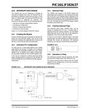
引脚图在P6P11P12P13P14P131P204P206P213P322Hot
典型应用电路图在P137P323
原理图在P10P16P52P63P73P97P131P135P139P154P158P164
封装尺寸在P384
标记信息在P383
封装信息在P383P385P386P390P391
功能描述在P315
技术参数、封装参数在P54P58P84P98P102P135P140P146P150P153P167P168
应用领域在P47P54P55P215P222
电气规格在P54P58P84P98P135P140P146P150P153P167P169P175


导航目录
PIC16F1827T-E/SS数据手册
Page:
of 406 Go
若手册格式错乱,请下载阅览PDF原文件
2011 Microchip Technology Inc. DS41391D-page 131
PIC16(L)F1826/27
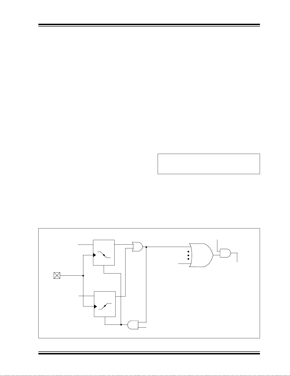
13.0 INTERRUPT-ON-CHANGE
The PORTB pins can be configured to operate as
Interrupt-On-Change (IOC) pins. An interrupt can be
generated by detecting a signal that has either a rising
edge or a falling edge. Any individual PORTB pin can
be configured to generate an interrupt. The
interrupt-on-change module has the following features:
• Interrupt-on-Change enable (Master Switch)
• Individual pin configuration
• Rising and falling edge detection
• Individual pin interrupt flags
Figure 13-1 is a block diagram of the IOC module.
13.1 Enabling the Module
To allow individual port pins to generate an interrupt, the
IOCIE bit of the INTCON register must be set. If the
IOCIE bit is disabled, the edge detection on the pin will
still occur, but an interrupt will not be generated.
13.2 Individual Pin Configuration
For each port pin, a rising edge detector and a falling
edge detector are present. To enable a pin to detect a
rising edge, the associated IOCBPx bit of the IOCBP
register is set. To enable a pin to detect a falling edge,
the associated IOCBNx bit of the IOCBN register is set.
A pin can be configured to detect rising and falling
edges simultaneously by setting both the IOCBPx bit
and the IOCBNx bit of the IOCBP and IOCBN registers,
respectively.
13.3 Interrupt Flags
The IOCBFx bits located in the IOCBF register are
status flags that correspond to the Interrupt-on-change
pins of the port. If an expected edge is detected on an
appropriately enabled pin, then the status flag for that pin
will be set, and an interrupt will be generated if the IOCIE
bit is set. The IOCIF bit of the INTCON register reflects
the status of all IOCBFx bits.
13.4 Clearing Interrupt Flags
The individual status flags, (IOCBFx bits), can be
cleared by resetting them to zero. If another edge is
detected during this clearing operation, the associated
status flag will be set at the end of the sequence,
regardless of the value actually being written.
In order to ensure that no detected edge is lost while
clearing flags, only AND operations masking out known
changed bits should be performed. The following
sequence is an example of what should be performed.
EXAMPLE 13-1:
13.5 Operation in Sleep
The interrupt-on-change interrupt sequence will wake
the device from Sleep mode, if the IOCIE bit is set.
If an edge is detected while in Sleep mode, the IOCBF
register will be updated prior to the first instruction
executed out of Sleep.
FIGURE 13-1: INTERRUPT-ON-CHANGE BLOCK DIAGRAM
MOVLW 0xff
XORWF IOCBF, W
ANDWF IOCBF, F
RBx
From all other IOCBFx
individual pin detectors
DQ
CK
R
DQ
CK
R
IOCBNx
IOCBPx
Q2 Clock Cycle
IOCIE
IOC Interrupt to
CPU Core
IOCBFx
器件 Datasheet 文档搜索
AiEMA 数据库涵盖高达 72,405,303 个元件的数据手册,每天更新 5,000 多个 PDF 文件
