Datasheet 搜索 > Microchip(微芯) > PIC16F1827T-E/SS 数据手册 > PIC16F1827T-E/SS 数据手册 135/406 页
 器件3D模型
¥ 0
PIC16F1827T-E/SS 数据手册 - Microchip(微芯)
制造商:
Microchip(微芯)
封装:
SSOP-20
描述:
18 /20/ 28引脚闪存单片机采用纳瓦XLP技术 18/20/28-Pin Flash Microcontrollers with nanoWatt XLP Technology
Pictures:
3D模型
符号图
焊盘图
引脚图
产品图
页面导航:
引脚图在P6P11P12P13P14P131P204P206P213P322Hot
典型应用电路图在P137P323
原理图在P10P16P52P63P73P97P131P135P139P154P158P164
封装尺寸在P384
标记信息在P383
封装信息在P383P385P386P390P391
功能描述在P315
技术参数、封装参数在P54P58P84P98P102P135P140P146P150P153P167P168
应用领域在P47P54P55P215P222
电气规格在P54P58P84P98P135P140P146P150P153P167P169P175

导航目录
PIC16F1827T-E/SS数据手册
Page:
of 406 Go
若手册格式错乱,请下载阅览PDF原文件
2011 Microchip Technology Inc. DS41391D-page 135
PIC16(L)F1826/27
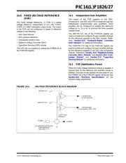
14.0 FIXED VOLTAGE REFERENCE
(FVR)
The Fixed Voltage Reference, or FVR, is a stable
voltage reference, independent of V
DD, with 1.024V,
2.048V or 4.096V selectable output levels. The output
of the FVR can be configured to supply a reference
voltage to the following:
• ADC input channel
• ADC positive reference
• Comparator positive input
• Digital-to-Analog Converter (DAC)
• Capacitive Sensing (CPS) module
The FVR can be enabled by setting the FVREN bit of
the FVRCON register.
14.1 Independent Gain Amplifiers
The output of the FVR supplied to the ADC,
Comparators, and DAC and CPS is routed through two
independent programmable gain amplifiers. Each
amplifier can be configured to amplify the reference
voltage by 1x, 2x or 4x, to produce the three possible
voltage levels.
The ADFVR<1:0> bits of the FVRCON register are
used to enable and configure the gain amplifier settings
for the reference supplied to the ADC module. Refer-
ence Section 16.0 “Analog-to-Digital Converter
(ADC) Module” for additional information.
The CDAFVR<1:0> bits of the FVRCON register are
used to enable and configure the gain amplifier settings
for the reference supplied to the DAC and comparator
module. Reference Section 16.0 “Digital-to-Analog
Converter (DAC) Module” and Section 18.0 “Com-
parator Module” and Section 27.0 “Capacitive
Sensing Module” for additional information.
14.2 FVR Stabilization Period
When the Fixed Voltage Reference module is enabled, it
requires time for the reference and amplifier circuits to
stabilize. Once the circuits stabilize and are ready for use,
the FVRRDY bit of the FVRCON register will be set. See
Section 30.0 “Electrical Specifications” for the
minimum delay requirement.
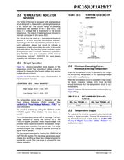
FIGURE 14-1: VOLTAGE REFERENCE BLOCK DIAGRAM
ADFVR<1:0>
CDAFVR<1:0>
X1
X2
X4
X1
X2
X4
2
2
FVR BUFFER1
(To ADC Module)
FVR BUFFER2
(To Comparators, DAC, CPS)
+
_
FVREN
FVRRDY
1.024V Fixed
Reference
Any peripheral requiring the
Fixed Reference
(See Table 14-1)
器件 Datasheet 文档搜索
AiEMA 数据库涵盖高达 72,405,303 个元件的数据手册,每天更新 5,000 多个 PDF 文件
