Datasheet 搜索 > Microchip(微芯) > PIC16F1827T-E/SS 数据手册 > PIC16F1827T-E/SS 数据手册 204/406 页
 器件3D模型
¥ 0
PIC16F1827T-E/SS 数据手册 - Microchip(微芯)
制造商:
Microchip(微芯)
封装:
SSOP-20
描述:
18 /20/ 28引脚闪存单片机采用纳瓦XLP技术 18/20/28-Pin Flash Microcontrollers with nanoWatt XLP Technology
Pictures:
3D模型
符号图
焊盘图
引脚图
产品图
页面导航:
引脚图在P6P11P12P13P14P131P204P206P213P322Hot
典型应用电路图在P137P323
原理图在P10P16P52P63P73P97P131P135P139P154P158P164
封装尺寸在P384
标记信息在P383
封装信息在P383P385P386P390P391
功能描述在P315
技术参数、封装参数在P54P58P84P98P102P135P140P146P150P153P167P168
应用领域在P47P54P55P215P222
电气规格在P54P58P84P98P135P140P146P150P153P167P169P175
导航目录
PIC16F1827T-E/SS数据手册
Page:
of 406 Go
若手册格式错乱,请下载阅览PDF原文件
PIC16(L)F1826/27
DS41391D-page 204 2011 Microchip Technology Inc.
24.1 Capture Mode
The Capture mode function described in this section is
available and identical for CCP modules ECCP1,
ECCP2, CCP3 and CCP4.
Capture mode makes use of the 16-bit Timer1
resource. When an event occurs on the CCPx pin, the
16-bit CCPRxH:CCPRxL register pair captures and
stores the 16-bit value of the TMR1H:TMR1L register
pair, respectively. An event is defined as one of the
following and is configured by the CCPxM<3:0> bits of
the CCPxCON register:
• Every falling edge
• Every rising edge
• Every 4th rising edge
• Every 16th rising edge
When a capture is made, the Interrupt Request Flag bit
CCPxIF of the PIRx register is set. The interrupt flag
must be cleared in software. If another capture occurs
before the value in the CCPRxH, CCPRxL register pair
is read, the old captured value is overwritten by the new
captured value.
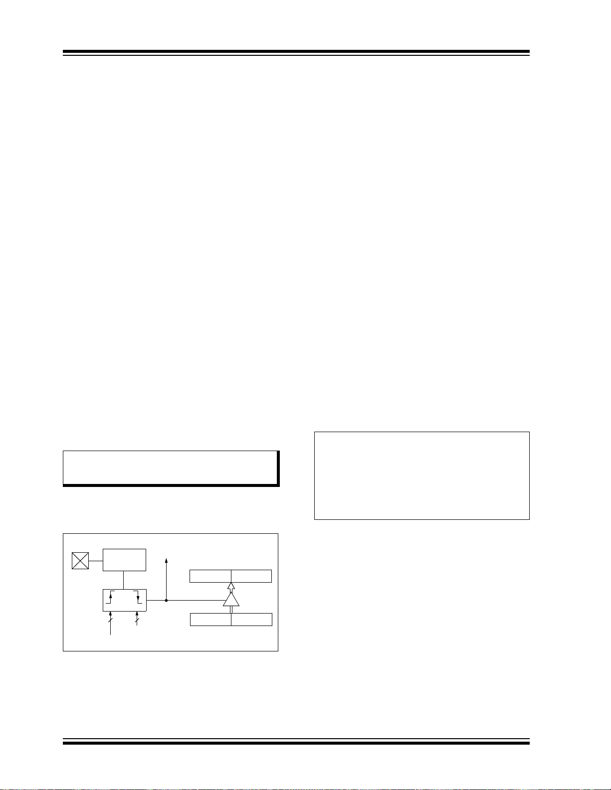
Figure 24-1 shows a simplified diagram of the Capture
operation.
24.1.1 CCP PIN CONFIGURATION
In Capture mode, the CCPx pin should be configured
as an input by setting the associated TRIS control bit.
Also, the CCPx pin function can be moved to
alternative pins using the APFCON0 register. Refer to
Section 12.1 “Alternate Pin Function” for more
details.
FIGURE 24-1: CAPTURE MODE
OPERATION BLOCK
DIAGRAM
24.1.2 TIMER1 MODE RESOURCE
Timer1 must be running in Timer mode or Synchronized
Counter mode for the CCP module to use the capture
feature. In Asynchronous Counter mode, the capture
operation may not work.
See Section 21.0 “Timer1 Module with Gate Control”
for more information on configuring Timer1.
24.1.3 SOFTWARE INTERRUPT MODE
When the Capture mode is changed, a false capture
interrupt may be generated. The user should keep the
CCPxIE interrupt enable bit of the PIEx register clear to
avoid false interrupts. Additionally, the user should
clear the CCPxIF interrupt flag bit of the PIRx register
following any change in Operating mode.
24.1.4 CCP PRESCALER
There are four prescaler settings specified by the
CCPxM<3:0> bits of the CCPxCON register. Whenever
the CCP module is turned off, or the CCP module is not
in Capture mode, the prescaler counter is cleared. Any
Reset will clear the prescaler counter.
Switching from one capture prescaler to another does not
clear the prescaler and may generate a false interrupt. To
avoid this unexpected operation, turn the module off by
clearing the CCPxCON register before changing the
prescaler. Equation 24-1 demonstrates the code to
perform this function.
EXAMPLE 24-1: CHANGING BETWEEN
CAPTURE PRESCALERS
Note: If the CCPx pin is configured as an output,
a write to the port can cause a capture
condition.
CCPRxH CCPRxL
TMR1H TMR1L
Set Flag bit CCPxIF
(PIRx register)
Capture
Enable
CCPxM<3:0>
Prescaler
1, 4, 16
and
Edge Detect
pin
CCPx
System Clock (F
OSC)
BANKSEL CCPxCON ;Set Bank bits to point
;to CCPxCON
CLRF CCPxCON ;Turn CCP module off
MOVLW NEW_CAPT_PS;Load the W reg with
;the new prescaler
;move value and CCP ON
MOVWF CCPxCON ;Load CCPxCON with this
;value
器件 Datasheet 文档搜索
AiEMA 数据库涵盖高达 72,405,303 个元件的数据手册,每天更新 5,000 多个 PDF 文件
