Datasheet 搜索 > 微控制器 > Microchip(微芯) > PIC16F628-20/SO 数据手册 > PIC16F628-20/SO 数据手册 64/171 页
 器件3D模型
¥ 28.673
PIC16F628-20/SO 数据手册 - Microchip(微芯)
制造商:
Microchip(微芯)
分类:
微控制器
封装:
SOIC-18
描述:
PIC16F627/628 8 位闪存微控制器Microchip 的 PIC16F 系列微控制器 8 位 MCU,将 Microchip 的 PIC® 体系架构融入到引脚和封装选件中,从节省空间的 14 引脚设备到功能丰富的 64 引脚设备。 带有基线、中级或增强型中级体系架构的设备提供多种不同的外围设备组合,可谓设计人员提供灵活性,并为应用提供选择。 PIC16F627/628 系列微控制器基于 Microchip 的中级内核,带 8 层深硬件堆栈和 35 个指令。 这些 MCU 提供高达 5 MIPS、高达 3.5 K 字节的程序内存,224 字节 RAM 和多达 128 字节的数据 EEPROM。### 微控制器功能最大 20 MHz CPU 速度 35 指令 8 级硬件堆栈 16 个输入/输出引脚 通电重置 (POR) 通电计时器 (PWRT) 振荡器启动计时器 (OST) 掉电重置 (BOR) 监控器计时器 (WDT) 在线串行编程 (ICSP) ### 外设两个比较器 捕获/比较/PWM 模块 两个 8 位计时器 一个 16 位计时器 通用同步接收器发送器 (USART) ### PIC16 微控制器
Pictures:
3D模型
符号图
焊盘图
引脚图
产品图
页面导航:
引脚图在P4P11P12P64Hot
原理图在P10P32P33P34P37P38P39P40P41P42P46P49
标记信息在P159
封装信息在P159P169
功能描述在P29
技术参数、封装参数在P50P97P98P108P135P137
应用领域在P97
电气规格在P50P97P98
导航目录
PIC16F628-20/SO数据手册
Page:
of 171 Go
若手册格式错乱,请下载阅览PDF原文件
PIC16F62X
DS40300C-page 62 Preliminary 2003 Microchip Technology Inc.
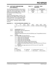
11.1 Capture Mode
In Capture mode, CCPR1H:CCPR1L captures the
16-bit value of the TMR1 register when an event occurs
on pin RB3/CCP1. An event is defined as:
• Every falling edge
• Every rising edge
• Every 4th rising edge
• Every 16th rising edge
An event is selected by control bits CCP1M3:CCP1M0
(CCP1CON<3:0>). When a capture is made, the Inter-
rupt Request Flag bit CCP1IF (PIR1<2>) is set. It must
be cleared in software. If another capture occurs before
the value in register CCPR1 is read, the old captured
value will be lost.
11.1.1 CCP PIN CONFIGURATION
In Capture mode, the RB3/CCP1 pin should be
configured as an input by setting the TRISB<3> bit.
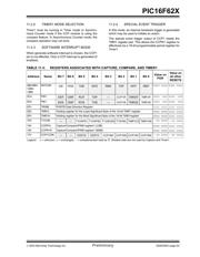
TABLE 11-2: CAPTURE MODE OPERATION
BLOCK DIAGRAM
11.1.2 TIMER1 MODE SELECTION
Timer1 must be running in Timer mode or Synchro-
nized Counter mode for the CCP module to use the
capture feature. In Asynchronous Counter mode, the
capture operation may not work.
11.1.3 SOFTWARE INTERRUPT
When the Capture mode is changed, a false capture
interrupt may be generated. The user should keep bit
CCP1IE (PIE1<2>) clear to avoid false interrupts and
should clear the flag bit CCP1IF following any such
change in Operating mode.
11.1.4 CCP PRESCALER
There are four prescaler settings, specified by bits
CCP1M3:CCP1M0. Whenever the CCP module is
turned off, or the CCP module is not in Capture mode,
the prescaler counter is cleared. This means that any
RESET will clear the prescaler counter.
Switching from one capture prescaler to another may
generate an interrupt. Also, the prescaler counter will
not be cleared, therefore the first capture may be from
a non-zero prescaler. Example 11-1 shows the
recommended method for switching between capture
prescalers. This example also clears the prescaler
counter and will not generate the “false” interrupt.
EXAMPLE 11-1: CHANGING BETWEEN
CAPTURE PRESCALERS
CLRF CCP1CON ;Turn CCP module off
MOVLW NEW_CAPT_PS ;Load the W reg with
; the new prescaler
; mode value and CCP ON
MOVWF CCP1CON ;Load CCP1CON with this
; value
11.2 Compare Mode
In Compare mode, the 16-bit CCPR1 register value is
constantly compared against the TMR1 register pair
value. When a match occurs, the RB3/CCP1 pin is:
• Driven High
• Driven Low
• Remains Unchanged
The action on the pin is based on the value of control
bits CCP1M3:CCP1M0 (CCP1CON<3:0>). At the
same time, interrupt flag bit CCP1IF is set.
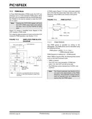
FIGURE 11-1: COMPARE MODE
OPERATION BLOCK
DIAGRAM
11.2.1 CCP PIN CONFIGURATION
The user must configure the RB3/CCP1 pin as an
output by clearing the TRISB<3> bit.
Note: If the RB3/CCP1 is configured as an out-
put, a write to the port can cause a capture
condition.
CCPR1H CCPR1L
TMR1H TMR1L
Set flag bit CCP1IF
(PIR1<2>)
Capture
Enable
Q’s
CCP1CON<3:0>
RB3/CCP1
Prescaler
³ 1, 4, 16
and
edge detect
Pin
Note: Clearing the CCP1CON register will force
the RB3/CCP1 compare output latch to the
default low level. This is not the data latch.
CCPR1H CCPR1L
TMR1H TMR1L
Comparator
QS
R
Output
Logic
Set flag bit CCP1IF
(PIR1<2>)
match
RB3/CCP1
TRISB<3>
CCP1CON<3:0>
Mode Select
Output Enable
Pin
Special Event Trigger will reset Timer1, but not set
interrupt flag bit TMR1IF (PIR1<0>)
器件 Datasheet 文档搜索
AiEMA 数据库涵盖高达 72,405,303 个元件的数据手册,每天更新 5,000 多个 PDF 文件
