Datasheet 搜索 > 微控制器 > Microchip(微芯) > PIC16F884-I/P 数据手册 > PIC16F884-I/P 数据手册 3/328 页
 器件3D模型
¥ 12.287
PIC16F884-I/P 数据手册 - Microchip(微芯)
制造商:
Microchip(微芯)
分类:
微控制器
封装:
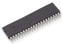
DIP-40
描述:
PIC16F882/883/884/886/887 8 位闪存微控制器Microchip 的 PIC16F 系列微控制器 8 位 MCU,将 Microchip 的 PIC® 体系架构融入到引脚和封装选件中,从节省空间的 14 引脚设备到功能丰富的 64 引脚设备。 带有基线、中级或增强型中级体系架构的设备提供多种不同的外围设备组合,可谓设计人员提供灵活性,并为应用提供选择。 PIC16F882/883/884/886/887 系列微控制器基于 Microchip 的中级内核,带 8 层深硬件堆栈和 35 个指令。 这些 MCU 提供高达 5 个 MIP、14 千字节程序存储器、368 字节 RAM 和 256 字节 EEPROM。 板载是一个可配置振荡器,工厂校准到 ±1% 精确度。### 微控制器功能最大 20 MHz CPU 速度 35 指令 8 级硬件堆栈 8 MHz 内部振荡器 - 可选输出范围 8 MHz 至 31 kHz 24 个输入/输出引脚 –PIC16F882/883/886 35 个输入/输出引脚 –PIC16F884/887 通电重置 (POR) 掉电重置 (BOR) 通电计时器 (PWRT) 振荡器启动计时器 (OST) 监控器计时器 (WDT) 在线串行编程 (ICSP) 在线调试 (ICD) ### 外设10 位模拟到数字转换器 (ADC) - PIC16F882/883/886 11 通道,PIC16F884/887 14 通道 两个捕获、比较、PWM (CCP) 模块 增强型捕获、比较、PWM (ECCP) 模块 两个比较器 两个 8 位计时器 一个 16 位计时器 主同步串行端口 (MSSP),带有 SPI 和 I2C 增强型通用同步异步接收器发射器 (EUSART) ### PIC16 微控制器展开
Pictures:
3D模型
符号图
焊盘图
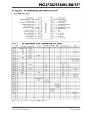
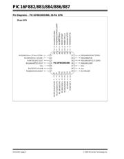
引脚图
产品图
页面导航:
引脚图在P5P6P8P10P12P18P19P20P21P22P42P44Hot
原理图在P16P17P44P45P46P47P48P52P53P56P57P58
封装尺寸在P305
标记信息在P303P304
封装信息在P303
技术参数、封装参数在P69P76P87P89P92P96P102P110P214P215P216P224
应用领域在P66P137P146
电气规格在P69P76P87P89P92P96P102P110P214P215P216P224
导航目录
PIC16F884-I/P数据手册
Page:
of 328 Go
若手册格式错乱,请下载阅览PDF原文件

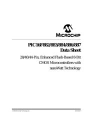
© 2009 Microchip Technology Inc. DS41291F-page 1
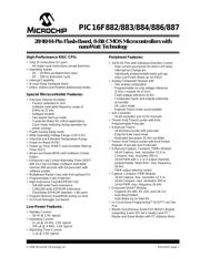
PIC16F882/883/884/886/887
High-Performance RISC CPU:
• Only 35 Instructions to Learn:
- All single-cycle instructions except branches
• Operating Speed:
- DC – 20 MHz oscillator/clock input
- DC – 200 ns instruction cycle
• Interrupt Capability
• 8-Level Deep Hardware Stack
• Direct, Indirect and Relative Addressing modes
Special Microcontroller Features:
• Precision Internal Oscillator:
- Factory calibrated to ±1%
- Software selectable frequency range of
8 MHz to 31 kHz
- Software tunable
- Two-Speed Start-up mode
- Crystal fail detect for critical applications
- Clock mode switching during operation for
power savings
• Power-Saving Sleep mode
• Wide Operating Voltage Range (2.0V-5.5V)
• Industrial and Extended Temperature Range
• Power-on Reset (POR)
• Power-up Timer (PWRT) and Oscillator Start-up
Timer (OST)
• Brown-out Reset (BOR) with Software Control
Option
• Enhanced Low-Current Watchdog Timer (WDT)
with On-Chip Oscillator (software selectable
nominal 268 seconds with full prescaler) with
software enable
• Multiplexed Master Clear with Pull-up/Input Pin
• Programmable Code Protection
• High Endurance Flash/EEPROM Cell:
- 100,000 write Flash endurance
- 1,000,000 write EEPROM endurance
- Flash/Data EEPROM retention: > 40 years
• Program Memory Read/Write during run time
• In-Circuit Debugger (on board)
Low-Power Features:
• Standby Current:
- 50 nA @ 2.0V, typical
• Operating Current:
-11μA @ 32 kHz, 2.0V, typical
-220μA @ 4 MHz, 2.0V, typical
• Watchdog Timer Current:
-1μA @ 2.0V, typical
Peripheral Features:
• 24/35 I/O Pins with Individual Direction Control:
- High current source/sink for direct LED drive
- Interrupt-on-Change pin
- Individually programmable weak pull-ups
- Ultra Low-Power Wake-up (ULPWU)
• Analog Comparator Module with:
- Two analog comparators
- Programmable on-chip voltage reference
(CV
REF) module (% of VDD)
- Fixed voltage reference (0.6V)
- Comparator inputs and outputs externally
accessible
- SR Latch mode
- External Timer1 Gate (count enable)
• A/D Converter:
- 10-bit resolution and 11/14 channels
• Timer0: 8-bit Timer/Counter with 8-bit
Programmable Prescaler
• Enhanced Timer1:
- 16-bit timer/counter with prescaler
- External Gate Input mode
- Dedicated low-power 32 kHz oscillator
• Timer2: 8-bit Timer/Counter with 8-bit Period
Register, Prescaler and Postscaler
• Enhanced Capture, Compare, PWM+ Module:
- 16-bit Capture, max. resolution 12.5 ns
- Compare, max. resolution 200 ns
- 10-bit PWM with 1, 2 or 4 output channels,
programmable “dead time”, max. frequency
20 kHz
- PWM output steering control
• Capture, Compare, PWM Module:
- 16-bit Capture, max. resolution 12.5 ns
- 16-bit Compare, max. resolution 200 ns
- 10-bit PWM, max. frequency 20 kHz
• Enhanced USART Module:
- Supports RS-485, RS-232, and LIN 2.0
- Auto-Baud Detect
- Auto-Wake-Up on Start bit
• In-Circuit Serial Programming
TM
(ICSP
TM
) via Two
Pins
• Master Synchronous Serial Port (MSSP) Module
supporting 3-wire SPI (all 4 modes) and I
2
C™
Master and Slave Modes with I
2
C Address Mask
28/40/44-Pin Flash-Based, 8-Bit CMOS Microcontrollers with
nanoWatt Technology
器件 Datasheet 文档搜索
AiEMA 数据库涵盖高达 72,405,303 个元件的数据手册,每天更新 5,000 多个 PDF 文件
