Datasheet 搜索 > 8位微控制器 > Microchip(微芯) > PIC18F1220-E/P 数据手册 > PIC18F1220-E/P 数据手册 1/8 页
 器件3D模型
¥ 2.507
PIC18F1220-E/P 数据手册 - Microchip(微芯)
制造商:
Microchip(微芯)
分类:
8位微控制器
封装:
PDIP-18
描述:
MICROCHIP PIC18F1220-E/P 微控制器, 8位, 闪存, PIC18F1xxx, 40 MHz, 4 KB, 256 Byte, 18 引脚, DIP
Pictures:
3D模型
符号图
焊盘图
引脚图
产品图


PIC18F1220-E/P数据手册
Page:
of 8 Go
若手册格式错乱,请下载阅览PDF原文件
© 2006 Microchip Technology Inc. DS80160F-page 1
PIC18F1220/1320
The PIC18F1220/1320 Rev. B1 parts you have received
conform functionally to the Device Data Sheet
(DS39605C), except for the anomalies described below.
All of the issues listed here will be addressed in future
revisions of the PIC18F1220/1320 silicon.
The following silicon errata apply only to
PIC18F1220/1320 devices with these Device/Revision
IDs:
1. Module: Core
Certain combinations of code sequence, code
placement, V
DD, FOSC and temperature may cause
the corruption of fetched instructions. A corrupted
instruction fetch will cause the part to execute an
incorrect instruction with unpredictable results.
Microchip cannot predict which combinations of
these conditions will cause this failure.
If this failure mechanism exists in your system, it
should become evident during statistically significant
preproduction testing using your particular code
sequence and placement (the minimum suggested
sample size is 100 units). Preproduction testing
should exercise all the functions of your application
across system variables. Any changes to code
should be tested in the same manner prior to being
implemented.
This issue has not been observed for F
OSC up to
4 MHz with V
DD up to 5.25V. If failures occur while
meeting both of these conditions, then the failures
are likely not related to this failure mechanism.
Work around
Use the part at or below 4 MHz with VDD at or
below 5.25V.
Change the placement of code within program
memory.
Use the next revision of silicon when it becomes
available.
Date Codes that pertain to this issue:
All engineering and production devices.
2. Module: Data EEPROM
When reading the data EEPROM, the contents of
the EEDATA register may be corrupted if the RD
bit (EECON1<0>) is set immediately following a
write to the address byte (EEADR). The actual
contents of the data EEPROM remain unaffected.
Work around
Do not set EEADR immediately before the
execution of a read. Write to EEADR at least one
instruction cycle before setting the RD bit. The
instruction between the write to EEADR and the
read can be any valid instruction, including a NOP.
Date Codes that pertain to this issue:
All engineering and production devices.
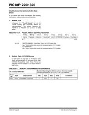
3. Module: Core (DAW Instruction)
The DAW instruction may improperly clear the
Carry bit (STATUS<0>) when executed.
Work around
Test the Carry bit state before executing the DAW
instruction. If the Carry bit is set, increment the
next higher byte to be added, using an instruction
such as INCFSZ (this instruction does not affect
any Status flags and will not overflow a BCD nib-
ble). After the DAW instruction has been executed,
process the Carry bit normally (see Example 1).
EXAMPLE 1: PROCESSING THE CARRY
BIT DURING BCD ADDITIONS
Date Codes that pertain to this issue:
All engineering and production devices.
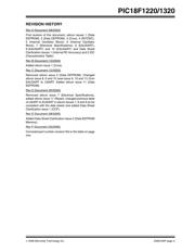
Part Number Device ID Revision ID
PIC18F1220 00 0111 111 00010
PIC18F1320 00 0111 110 00010
The Device IDs (DEVID1 and DEVID2) are located at
addresses 3FFFFEh:3FFFFFh in the device’s
configuration space. They are shown in hexadecimal
in the format “DEVID2 DEVID1”.
MOVLW 0x80 ; .80 (BCD)
ADDLW 0x80 ; .80 (BCD)
BTFSC STATUS, C ; test C
INCFSZ byte2 ; inc next higher LSB
DAW
BTFSC STATUS, C ; test C
INCFSZ byte2 ; inc next higher LSB
This is repeated for each DAW instruction.
PIC18F1220/1320 Rev. B1 Silicon/Data Sheet Errata
器件 Datasheet 文档搜索
AiEMA 数据库涵盖高达 72,405,303 个元件的数据手册,每天更新 5,000 多个 PDF 文件
