Datasheet 搜索 > 微控制器 > Microchip(微芯) > PIC18F1320-I/ML 数据手册 > PIC18F1320-I/ML 数据手册 2/8 页
 器件3D模型
¥ 40.62
PIC18F1320-I/ML 数据手册 - Microchip(微芯)
制造商:
Microchip(微芯)
分类:
微控制器
封装:
QFN-28
描述:
PIC18F1220/1320 8 位微控制器### PIC18 微控制器
Pictures:
3D模型
符号图
焊盘图
引脚图
产品图


PIC18F1320-I/ML数据手册
Page:
of 8 Go
若手册格式错乱,请下载阅览PDF原文件

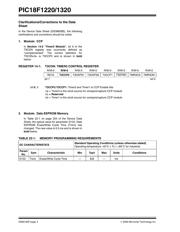
PIC18F1220/1320
DS80160F-page 2 © 2006 Microchip Technology Inc.
4. Module: INTOSC
Incrementing or decrementing the value in the
OSCTUNE register may not have the expected
effect of shifting the INTRC or INTOSC output
frequencies. The OSCTUNE values for which this
happens may vary with temperatures above 70°C.
Work around
None
Date Codes that pertain to this issue:
All engineering and production devices.
5. Module: Internal Oscillator Block
At high temperature (above 85°C) or low VDD
(below 2.5V), the IOFS bit (OSCCON<2>) may not
become set when the internal oscillator block is
selected as the system clock source for any
frequency above 31 kHz (OSCCON<6:4>
≠ 000).
The INTOSC output will stabilize at 8 MHz;
however, the IOFS bit may not become set.
Work around
If time critical code is to be executed, it should be
delayed by 1 ms following the operation that
enables the 8 MHz INTOSC output from the
internal oscillator block.
Date Codes that pertain to this issue:
All engineering and production devices.
6. Module: Internal Oscillator Block
If the INTRC clock source was not started at POR
(any V
DD) and VDD is greater than 4.5V, the INTRC
clock source may not start or may require a long
delay when starting. The INTRC may not restart
when V
DD is lowered below 4.5V.
Features that depend on the operation of the
INTRC clock source may be affected. These
include the INTOSC output when exiting from
Sleep mode, the Watchdog Timer (WDT) if
enabled by firmware using the WDTCON register,
Two-Speed Start-ups during Reset or wake-up
from Sleep and the Fail-Safe Clock Monitor
(FSCM) when exiting Sleep mode.
The INTOSC frequency may rise very high (for
example, 9.5 MHz). The WDT and the FSCM may
simply not function. Two-Speed Start-ups may not
occur but execution will start once the primary
clock source becomes ready.
Work around
Several work arounds may be used.
1. Enable the WDT in Configuration register,
CONFIG2H, and place a CLRWDT instruction
somewhere in the main loop.
2. Configure the internal oscillator block as the
primary clock source using Configuration
Register 1H.
3. Any technique that starts the INTRC at Reset
and does not disable it may be used.
4. Ensure that V
DD is below 4.5V when starting
the INTRC clock source.
There may be other work arounds.
Date Codes that pertain to this issue:
All engineering and production devices.
器件 Datasheet 文档搜索
AiEMA 数据库涵盖高达 72,405,303 个元件的数据手册,每天更新 5,000 多个 PDF 文件
