Datasheet 搜索 > 微控制器 > Microchip(微芯) > PIC18F25K22-I/SO 数据手册 > PIC18F25K22-I/SO 数据手册 132/539 页
 器件3D模型
¥ 20.347
PIC18F25K22-I/SO 数据手册 - Microchip(微芯)
制造商:
Microchip(微芯)
分类:
微控制器
封装:
SOIC-28
描述:
PIC18F2xK22/4xK22 8 位闪存微控制器### PIC18 微控制器
Pictures:
3D模型
符号图
焊盘图
引脚图
产品图
页面导航:
引脚图在P132P174P177P185Hot
典型应用电路图在P321P322
原理图在P14P26P28P42P55P155P156P157P160P169P174P177
封装尺寸在P512
标记信息在P509P510P511
封装信息在P509P513P514P515P517P521P522P525P526P527P528P529
技术参数、封装参数在P11P12P36P40P102P237P300P304P306P307P333P339
应用领域在P187P193P341
电气规格在P11P12P36P40P102P300P304P306P307P333P339

导航目录
PIC18F25K22-I/SO数据手册
Page:
of 539 Go
若手册格式错乱,请下载阅览PDF原文件

PIC18(L)F2X/4XK22
DS40001412G-page 132 2010-2016 Microchip Technology Inc.
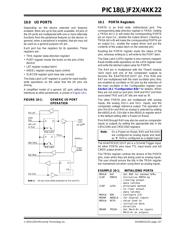
10.2 PORTB Registers
PORTB is an 8-bit wide, bidirectional port. The
corresponding data direction register is TRISB. Setting
a TRISB bit (= 1) will make the corresponding PORTB
pin an input (i.e., disable the output driver). Clearing a
TRISB bit (= 0) will make the corresponding PORTB
pin an output (i.e., enable the output driver and put the
contents of the output latch on the selected pin).
The Data Latch register (LATB) is also memory
mapped. Read-modify-write operations on the LATB
register read and write the latched output value for
PORTB.
EXAMPLE 10-2: INITIALIZING PORTB
10.2.1 PORTB OUTPUT PRIORITY
Each PORTB pin is multiplexed with other functions.
The pins, their combined functions and their output
priorities are briefly described here. For additional
information, refer to the appropriate section in this data
sheet.
When multiple outputs are enabled, the actual pin
control goes to the peripheral with the higher priority.
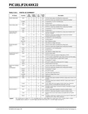
Table 10-4 lists the PORTB pin functions from the
highest to the lowest priority.
Analog input functions, such as ADC, comparator and
SR latch inputs, are not shown in the priority lists.
These inputs are active when the I/O pin is set for
Analog mode using the ANSELx registers. Digital
output functions may control the pin when it is in Analog
mode with the priority shown below.
10.3 Additional PORTB Pin Functions
PORTB pins RB<7:4> have an interrupt-on-change
option. All PORTB pins have a weak pull-up option.
10.3.1 WEAK PULL-UPS
Each of the PORTB pins has an individually controlled
weak internal pull-up. When set, each bit of the WPUB
register enables the corresponding pin pull-up. When
cleared, the RBPU
bit of the INTCON2 register enables
pull-ups on all pins which also have their corresponding
WPUB bit set. When set, the RBPU bit disables all
weak pull-ups. The weak pull-up is automatically turned
off when the port pin is configured as an output. The
pull-ups are disabled on a Power-on Reset.
10.3.2 INTERRUPT-ON-CHANGE
Four of the PORTB pins (RB<7:4>) are individually
configurable as interrupt-on-change pins. Control bits
in the IOCB register enable (when set) or disable (when
clear) the interrupt function for each pin.
When set, the RBIE bit of the INTCON register enables
interrupts on all pins which also have their
corresponding IOCB bit set. When clear, the RBIE bit
disables all interrupt-on-changes.
Only pins configured as inputs can cause this interrupt
to occur (i.e., any RB<7:4> pin configured as an output
is excluded from the interrupt-on-change comparison).
For enabled interrupt-on-change pins, the values are
compared with the old value latched on the last read of
PORTB. The ‘mismatch’ outputs of the last read are
OR’d together to set the PORTB Change Interrupt flag
bit (RBIF) in the INTCON register.
This interrupt can wake the device from the Sleep
mode, or any of the Idle modes. The user, in the
Interrupt Service Routine, can clear the interrupt in the
following manner:
a) Any read or write of PORTB to clear the mis-
match condition (except when PORTB is the
source or destination of a MOVFF instruction).
b) Execute at least one instruction after reading or
writing PORTB, then clear the flag bit, RBIF.
MOVLB 0xF ; Set BSR for banked SFRs
CLRF PORTB ; Initialize PORTB by
; clearing output
; data latches
CLRF LATB ; Alternate method
; to clear output
; data latches
MOVLW 0F0h ; Value for init
MOVWF ANSELB ; Enable RB<3:0> for
; digital input pins
; (not required if config bit
; PBADEN is clear)
MOVLW 0CFh ; Value used to
; initialize data
; direction
MOVWF TRISB ; Set RB<3:0> as inputs
; RB<5:4> as outputs
; RB<7:6> as inputs
Note: On a Power-on Reset, RB<5:0> are
configured as analog inputs by default and
read as ‘0’; RB<7:6> are configured as
digital inputs.
When the PBADEN Configuration bit is
set to ‘1’, RB<5:0> will alternatively be
configured as digital inputs on POR.
器件 Datasheet 文档搜索
AiEMA 数据库涵盖高达 72,405,303 个元件的数据手册,每天更新 5,000 多个 PDF 文件
