Datasheet 搜索 > 微控制器 > Microchip(微芯) > PIC18F4620-E/P 数据手册 > PIC18F4620-E/P 数据手册 27/412 页
 器件3D模型
¥ 93.559
PIC18F4620-E/P 数据手册 - Microchip(微芯)
制造商:
Microchip(微芯)
分类:
微控制器
封装:
PDIP-40
描述:
PIC18 系列 3986 B RAM 64 kB 闪存 8位 微控制器 - PDIP-40
Pictures:
3D模型
符号图
焊盘图
引脚图
产品图
页面导航:
引脚图在P4P5P142P143P144P150Hot
典型应用电路图在P167
原理图在P10P12P13P27P43P108P126P130P136P138P143P144
封装尺寸在P387
标记信息在P385P386
封装信息在P385
技术参数、封装参数在P338P340P343P344P345
应用领域在P154P248
电气规格在P9P10P75P236P237P241P242P245
导航目录
PIC18F4620-E/P数据手册
Page:
of 412 Go
若手册格式错乱,请下载阅览PDF原文件
© 2008 Microchip Technology Inc. DS39626E-page 25
PIC18F2525/2620/4525/4620
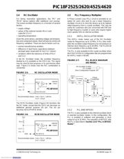
2.4 RC Oscillator
For timing insensitive applications, the “RC” and
“RCIO” device options offer additional cost savings.
The actual oscillator frequency is a function of several
factors:
• supply voltage
• values of the external resistor (R
EXT) and
capacitor (C
EXT)
• operating temperature
Given the same device, operating voltage and tempera-
ture and component values, there will also be unit-to-unit
frequency variations. These are due to factors such as:
• normal manufacturing variation
• difference in lead frame capacitance between
package types (especially for low C
EXT values)
• variations within the tolerance of limits of R
EXT
and C
EXT
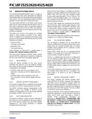
In the RC Oscillator mode, the oscillator frequency
divided by 4 is available on the OSC2 pin. This signal
may be used for test purposes or to synchronize other
logic. Figure 2-5 shows how the R/C combination is
connected.
FIGURE 2-5: RC OSCILLATOR MODE
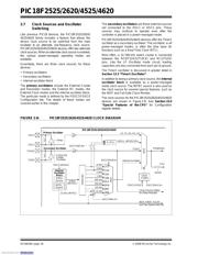
The RCIO Oscillator mode (Figure 2-6) functions like
the RC mode, except that the OSC2 pin becomes an
additional general purpose I/O pin. The I/O pin
becomes bit 6 of PORTA (RA6).
FIGURE 2-6: RCIO OSCILLATOR MODE
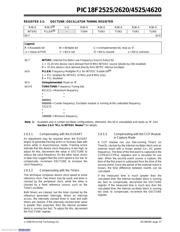
2.5 PLL Frequency Multiplier
A Phase Locked Loop (PLL) circuit is provided as an
option for users who wish to use a lower frequency
oscillator circuit or to clock the device up to its highest
rated frequency from a crystal oscillator. This may be
useful for customers who are concerned with EMI due
to high-frequency crystals or users who require higher
clock speeds from an internal oscillator.
2.5.1 HSPLL OSCILLATOR MODE
The HSPLL mode makes use of the HS Oscillator
mode for frequencies up to 10 MHz. A PLL then multi-
plies the oscillator output frequency by 4 to produce an
internal clock frequency up to 40 MHz. The PLLEN bit
is not available in this oscillator mode.
The PLL is only available to the crystal oscillator when
the FOSC3:FOSC0 Configuration bits are programmed
for HSPLL mode (= 0110).
FIGURE 2-7: PLL BLOCK DIAGRAM
(HS MODE)
2.5.2 PLL AND INTOSC
The PLL is also available to the internal oscillator block
in selected oscillator modes. In this configuration, the
PLL is enabled in software and generates a clock
output of up to 32 MHz. The operation of INTOSC with
the PLL is described in Section 2.6.4 “PLL in INTOSC
Modes”.
OSC2/CLKO
CEXT
REXT
PIC18FXXXX
OSC1
F
OSC/4
Internal
Clock
VDD
VSS
Recommended values: 3 kΩ ≤ REXT ≤ 100 kΩ
C
EXT > 20 pF
CEXT
REXT
PIC18FXXXX
OSC1
Internal
Clock
VDD
VSS
Recommended values: 3 kΩ ≤ REXT ≤ 100 kΩ
C
EXT > 20 pF
I/O (OSC2)
RA6
MUX
VCO
Loop
Filter
Crystal
Osc
OSC2
OSC1
PLL Enable
F
IN
FOUT
SYSCLK
Phase
Comparator
HS Oscillator Enable
÷4
(from Configuration Register 1H)
HS Mode
Downloaded from Arrow.com.Downloaded from Arrow.com.Downloaded from Arrow.com.Downloaded from Arrow.com.Downloaded from Arrow.com.Downloaded from Arrow.com.Downloaded from Arrow.com.Downloaded from Arrow.com.Downloaded from Arrow.com.Downloaded from Arrow.com.Downloaded from Arrow.com.Downloaded from Arrow.com.Downloaded from Arrow.com.Downloaded from Arrow.com.Downloaded from Arrow.com.Downloaded from Arrow.com.Downloaded from Arrow.com.Downloaded from Arrow.com.Downloaded from Arrow.com.Downloaded from Arrow.com.Downloaded from Arrow.com.Downloaded from Arrow.com.Downloaded from Arrow.com.Downloaded from Arrow.com.Downloaded from Arrow.com.Downloaded from Arrow.com.Downloaded from Arrow.com.
器件 Datasheet 文档搜索
AiEMA 数据库涵盖高达 72,405,303 个元件的数据手册,每天更新 5,000 多个 PDF 文件
