Datasheet 搜索 > Microchip(微芯) > PIC18LF4620T-E/PT 数据手册 > PIC18LF4620T-E/PT 数据手册 143/412 页

 器件3D模型
¥ 0
PIC18LF4620T-E/PT 数据手册 - Microchip(微芯)
制造商:
Microchip(微芯)
封装:
TQFP
Pictures:
3D模型
符号图
焊盘图
引脚图
产品图
页面导航:
引脚图在P4P5P142P143P144P150Hot
典型应用电路图在P167
原理图在P10P12P13P27P43P108P126P130P136P138P143P144
封装尺寸在P387
标记信息在P385P386
封装信息在P385
技术参数、封装参数在P338P340P343P344P345
应用领域在P154P248
电气规格在P9P10P75P236P237P241P242P245
导航目录
PIC18LF4620T-E/PT数据手册
Page:
of 412 Go
若手册格式错乱,请下载阅览PDF原文件
© 2008 Microchip Technology Inc. DS39626E-page 141
PIC18F2525/2620/4525/4620
15.2 Capture Mode
In Capture mode, the CCPRxH:CCPRxL register pair
captures the 16-bit value of the TMR1 or TMR3
registers when an event occurs on the corresponding
CCPx pin. An event is defined as one of the following:
• every falling edge
• every rising edge
• every 4th rising edge
• every 16th rising edge
The event is selected by the mode select bits,
CCPxM3:CCPxM0 (CCPxCON<3:0>). When a capture
is made, the interrupt request flag bit, CCPxIF, is set; it
must be cleared in software. If another capture occurs
before the value in register CCPRx is read, the old
captured value is overwritten by the new captured value.
15.2.1 CCP PIN CONFIGURATION
In Capture mode, the appropriate CCPx pin should be
configured as an input by setting the corresponding
TRIS direction bit.
15.2.2 TIMER1/TIMER3 MODE SELECTION
The timers that are to be used with the capture feature
(Timer1 and/or Timer3) must be running in Timer mode or
Synchronized Counter mode. In Asynchronous Counter
mode, the capture operation will not work. The timer to be
used with each CCP module is selected in the T3CON
register (see Section 15.1.1 “CCP Modules and Timer
Resources”).
15.2.3 SOFTWARE INTERRUPT
When the Capture mode is changed, a false capture
interrupt may be generated. The user should keep the
CCPxIE interrupt enable bit clear to avoid false
interrupts. The interrupt flag bit, CCPxIF, should also be
cleared following any such change in operating mode.
15.2.4 CCP PRESCALER
There are four prescaler settings in Capture mode; they
are specified as part of the operating mode selected by
the mode select bits (CCPxM3:CCPxM0). Whenever
the CCP module is turned off or Capture mode is
disabled, the prescaler counter is cleared. This means
that any Reset will clear the prescaler counter.
Switching from one capture prescaler to another may
generate an interrupt. Also, the prescaler counter will
not be cleared; therefore, the first capture may be from
a non-zero prescaler. Example 15-1 shows the
recommended method for switching between capture
prescalers. This example also clears the prescaler
counter and will not generate the “false” interrupt.
EXAMPLE 15-1: CHANGING BETWEEN
CAPTURE PRESCALERS
(CCP2 SHOWN)
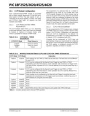
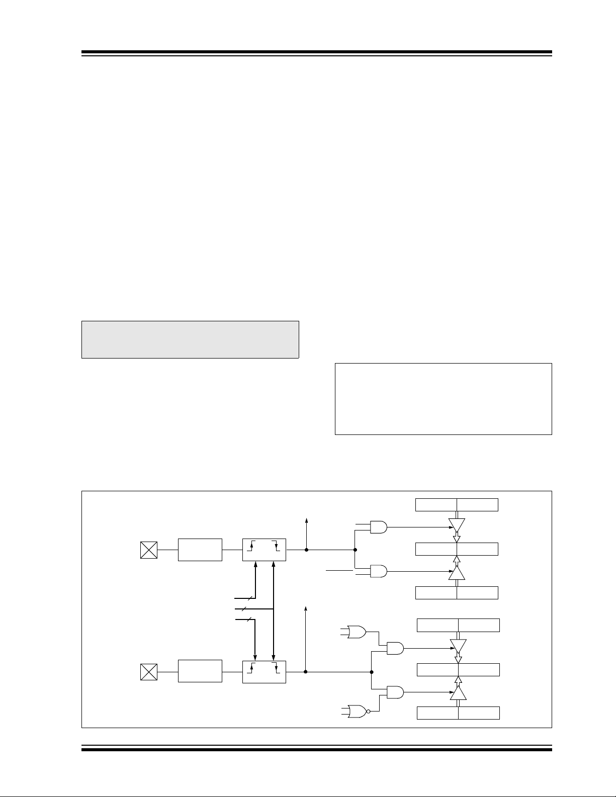
FIGURE 15-1: CAPTURE MODE OPERATION BLOCK DIAGRAM
Note: If RB3/CCP2 or RC1/CCP2 is configured
as an output, a write to the port can cause
a capture condition.
CLRF CCP2CON ; Turn CCP module off
MOVLW NEW_CAPT_PS ; Load WREG with the
; new prescaler mode
; value and CCP ON
MOVWF CCP2CON ; Load CCP2CON with
; this value
CCPR1H CCPR1L
TMR1H TMR1L
Set CCP1IF
TMR3
Enable
Q1:Q4
CCP1CON<3:0>
CCP1 pin
Prescaler
÷ 1, 4, 16
and
Edge Detect
TMR1
Enable
T3CCP2
T3CCP2
CCPR2H CCPR2L
TMR1H TMR1L
Set CCP2IF
TMR3
Enable
CCP2CON<3:0>
CCP2 pin
Prescaler
÷ 1, 4, 16
TMR3H TMR3L
TMR1
Enable
T3CCP2
T3CCP1
T3CCP2
T3CCP1
TMR3H TMR3L
and
Edge Detect
4
4
4
器件 Datasheet 文档搜索
AiEMA 数据库涵盖高达 72,405,303 个元件的数据手册,每天更新 5,000 多个 PDF 文件
