Datasheet 搜索 > 微控制器 > Microchip(微芯) > PIC24FV32KA304T-I/MV 数据手册 > PIC24FV32KA304T-I/MV 数据手册 163/364 页
 器件3D模型
¥ 35.184
PIC24FV32KA304T-I/MV 数据手册 - Microchip(微芯)
制造商:
Microchip(微芯)
分类:
微控制器
封装:
UQFN-48
描述:
PIC 32MHz 闪存:11K@x24bit RAM:2KB
Pictures:
3D模型
符号图
焊盘图
引脚图
产品图
页面导航:
引脚图在P3P4P5P6P7P16P17P18P19P20P21P22Hot
典型应用电路图在P232P233
原理图在P15P30P69P135P139P142P143P147P152P154P161P162
封装尺寸在P328
标记信息在P325
封装信息在P265P325P331P333P334P335P336P337P338P339P347P348
功能描述在P11P65P147P151P185
技术参数、封装参数在P265P272P273P274P275P276P278P280P293
应用领域在P127
电气规格在P25P72P74P206P219P243P248P352

导航目录
PIC24FV32KA304T-I/MV数据手册
Page:
of 364 Go
若手册格式错乱,请下载阅览PDF原文件
2011-2013 Microchip Technology Inc. DS39995D-page 163
PIC24FV32KA304 FAMILY
To set up the SPI1 module for the Enhanced Buffer
Master (EBM) mode of operation:
1. If using interrupts:
a) Clear the SPI1IF bit in the IFS0 register.
b) Set the SPI1IE bit in the IEC0 register.
c) Write the respective SPI1IPx bits in the
IPC2 register.
2. Write the desired settings to the SPI1CON1
and SPI1CON2 registers with the MSTEN bit
(SPI1CON1<5>) = 1.
3. Clear the SPIROV bit (SPI1STAT<6>).
4. Select Enhanced Buffer mode by setting the
SPIBEN bit (SPI1CON2<0>).
5. Enable SPI operation by setting the SPIEN bit
(SPI1STAT<15>).
6. Write the data to be transmitted to the SPI1BUF
register. Transmission (and reception) will start
as soon as data is written to the SPI1BUF
register.
To set up the SPI1 module for the Enhanced Buffer
Slave mode of operation:
1. Clear the SPI1BUF register.
2. If using interrupts:
a) Clear the SPI1IF bit in the IFS0 register.
b) Set the SPI1IE bit in the IEC0 register.
c) Write the respective SPI1IPx bits in the
IPC2 register to set the interrupt priority.
3. Write the desired settings to the SPI1CON1 and
SPI1CON2 registers with the MSTEN bit
(SPI1CON1<5>) = 0.
4. Clear the SMP bit.
5. If the CKE bit is set, then the SSEN bit must be
set, thus enabling the SS1
pin.
6. Clear the SPIROV bit (SPI1STAT<6>).
7. Select Enhanced Buffer mode by setting the
SPIBEN bit (SPI1CON2<0>).
8. Enable SPI operation by setting the SPIEN bit
(SPI1STAT<15>).
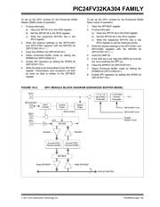
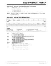
FIGURE 16-2: SPI1 MODULE BLOCK DIAGRAM (ENHANCED BUFFER MODE)
Internal Data Bus
SDI1
SDO1
SS1
/FSYNC1
SCK1
bit 0
Shift Control
Edge
Select
F
CY
Enable
SPI1BUF
Control
TransferTransfer
Write SPI1BUFRead SPI1BUF
16
SPI1CON1<1:0>
SPI1CON1<4:2>
Master Clock
Clock
Control
Primary
1:1/4/16/64
Prescaler
Secondary
Prescaler
1:1 to 1:8
Sync
SPI1SR
Transmit Buffer
8-Level FIFO
Receive Buffer
8-Level FIFO
器件 Datasheet 文档搜索
AiEMA 数据库涵盖高达 72,405,303 个元件的数据手册,每天更新 5,000 多个 PDF 文件
