Datasheet 搜索 > Littelfuse(力特) > Q4010NH5 数据手册 > Q4010NH5 数据手册 6/10 页


¥ 0
Q4010NH5 数据手册 - Littelfuse(力特)
制造商:
Littelfuse(力特)
描述:
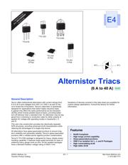
交变双向可控硅( 6 A到40 A ) Alternistor Triacs (6 A to 40 A)
Pictures:
3D模型
符号图
焊盘图
引脚图
产品图
页面导航:
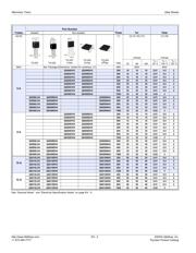
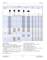
封装尺寸在P2P4P5P7
功能描述在P1
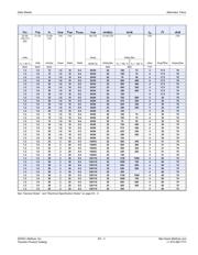
电气规格在P2P3P4P5
导航目录
Q4010NH5数据手册
Page:
of 10 Go
若手册格式错乱,请下载阅览PDF原文件
Alternistor Triacs Data Sheets
http://www.littelfuse.com E4 - 6 ©2004 Littelfuse, Inc.
+1 972-580-7777 Thyristor Product Catalog
(10) See Figure E4.12 for t
gt
versus I
GT
.
(11) See package outlines for lead form configurations. When ordering
special lead forming, add type number as suffix to part number.
(12) Initial on-state current = 400 mA dc for 16 A to 40 A devices and
100 mA for 6 A to 12 A devices.
(13) See Figure E4.1 through Figure E4.4 for maximum allowable case
temperature at maximum rated current.
(14) Pulse width ≤10 µs;
I
GT
≤ I
GTM
(15) For 6 A to 12 A devices, R
L
= 60 Ω; 16 A and above, R
L
= 30 Ω
(16) 40 A pin terminal leads on K package can run 100 °C to 125 °C.
(17) Alternistor does not turn on in Quadrant IV.
(18) T
C
= T
J
for test conditions in off state
(19) I
GT
= 200 mA for 6 A to 12 A devices and 500 mA for 16 A to 40 A
devices with gate pulse having rise time of ≤0.1 µs.
(20) Minimum non-trigger V
GT
at 125 °C is 0.2 V.
Gate Characteristics
Teccor triacs may be turned on in the following ways:
• In-phase signals (with standard AC line) using Quadrants I
and III
• Application of unipolar pulses (gate always negative), using
Quadrants II and III with negative gate pulses
In all cases, if maximum surge capability is required, gate pulses
should be a minimum of one magnitude above minimum I
GT
rat-
ing with a steep rising waveform (≤1 µs rise time).
If QIV and QI operation is required (gate always positive), see
Figure AN1002.8, “Amplified Gate” Thyristor Circuit.
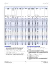
Definition of Quadrants
Electrical Isolation
Teccor’s isolated alternistor packages withstand a minimum high
potential test of 2500 V ac rms from leads to mounting tab, over
the operating temperature range of the device. The following iso-
lation table shows standard and optional isolation ratings.
* UL Recognized File E71639
** For 4000 V isolation, use V suffix in part number.
* UL Recognized Product per UL File E71639
** For 4000 V isolation, use V suffix in part number.
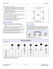
Electrical Isolation
from Leads to Mounting Tab *
VACRMS
TO-218
Isolated
TO-220
Isolated
TO-218X
Isolated
2500
Standard Standard Standard
4000
N/A Optional ** N/A
MT2 POSITIVE
(Positive Half Cycle)
MT2 NEGATIVE
(Negative Half Cycle)
MT1
MT2
+ I
GT
REF
QII
MT1
I
GT
GATE
MT2
REF
MT1
MT2
REF
MT1
MT2
REF
QI
QIV
QIII
ALL POLARITIES ARE REFERENCED TO MT1
(-)
I
GT
GATE
(+)
I
GT
-
I
GT
GATE
(-)
I
GT
GATE
(+)
+
-
NOTE: Alternistors will not operate in QIV
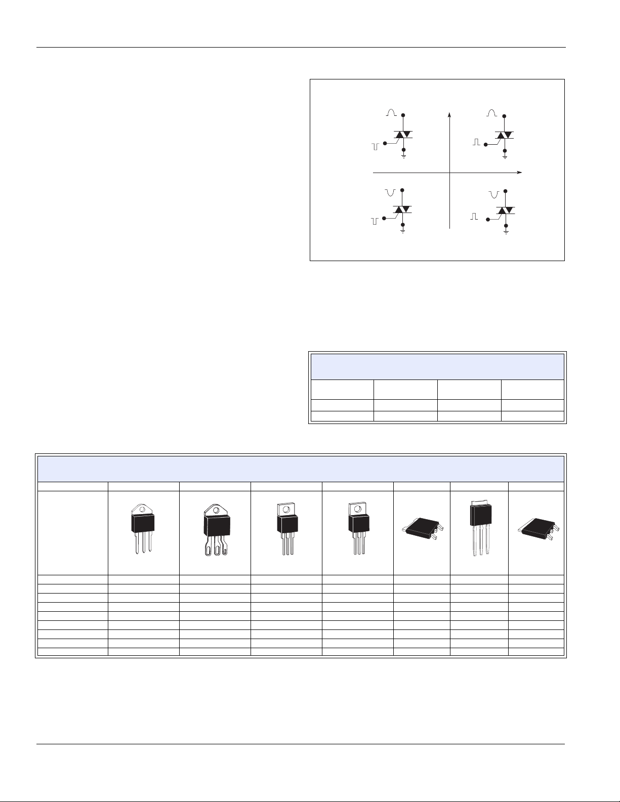
Thermal Resistance (Steady State)
R
θ JC
[R
θ JA
] (TYP.) °C/W
Package Code KJLRDVN
Type
TO-218
Isolated *
TO-218X
Isolated *
TO-220
Isolated **
TO-220
Non-Isolated
TO-252
D-Pak
TO-251
V-Pak
TO-263
D
2
Pak
6 A 3.3 [50] 1.80 [45] 2.1 2.3 [64] 1.80
8 A 2.8 1.50 1.8 2.1 1.50
10 A 2.6 1.30 1.30
12 A 2.3 1.20 1.20
16 A 2.1 1.10 1.10
25 A 1.35 1.32 2.0 0.87 0.87
30 A 2.3
35 A 0.85
40 A 0.97 0.95
器件 Datasheet 文档搜索
AiEMA 数据库涵盖高达 72,405,303 个元件的数据手册,每天更新 5,000 多个 PDF 文件
