Datasheet 搜索 > 电压基准芯片 > TI(德州仪器) > REF3212AIDBVTG4 数据手册 > REF3212AIDBVTG4 数据手册 8/19 页

¥ 34.125
REF3212AIDBVTG4 数据手册 - TI(德州仪器)
制造商:
TI(德州仪器)
分类:
电压基准芯片
封装:
SOT-23-6
描述:
TEXAS INSTRUMENTS REF3212AIDBVTG4 电压基准, 微功率, 低压降, 系列 - 固定, REF3212系列, 1.25V, SOT-23-6
Pictures:
3D模型
符号图
焊盘图
引脚图
产品图
页面导航:
引脚图在P2Hot
典型应用电路图在P11
原理图在P8
封装尺寸在P2P14P15
标记信息在P2P14P15
封装信息在P2P14P15P16
功能描述在P2P8
技术参数、封装参数在P2
应用领域在P1P4P16
电气规格在P3P4P8
导航目录
REF3212AIDBVTG4数据手册
Page:
of 19 Go
若手册格式错乱,请下载阅览PDF原文件

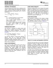
200
150
100
50
0
-50
-100
-150
-200
OutputVoltageStability(ppm)
0 400200 600 800 1000 1200
Time(Hours)
1
2
3
6
5
4
+2.5V
0.47 Fm
+5V
R32C
V
BANDGAP
Vbe
1
-
+
Vbe
2
-
+
R
1
Q
2
NQ
1
I
REF3212, REF3220
REF3225, REF3230
REF3233, REF3240
SBVS058C –JUNE 2005– REVISED AUGUST 2011
www.ti.com
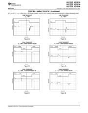
TYPICAL CHARACTERISTICS (continued)
At T
A
= +25°C, I
LOAD
= 0mA, V
IN
= +5V power supply, and REF3225 used for typical characteristics, unless otherwise noted.
LONG-TERM STABILITY
(32 Units)
Figure 19.
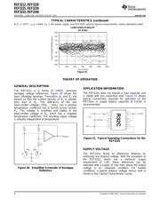
THEORY OF OPERATION
GENERAL DESCRIPTION
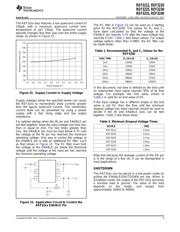
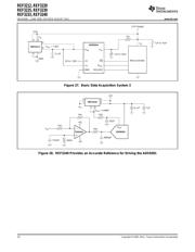
APPLICATION INFORMATION
The REF32xx is a family of CMOS, precision
The REF32xx does not require a load capacitor and
bandgap voltage references. Figure 20 shows the
is stable with any capacitive load. Figure 21 shows
basic bandgap topology. Transistors Q
1
and Q
2
are
typical connections required for operation of the
biased so that the current density of Q
1
is greater
REF32xx. A supply bypass capacitor of 0.47μF is
than that of Q
2
. The difference of the two
recommended.
base-emitter voltages (Vbe
1
– Vbe
2
) has a positive
temperature coefficient and is forced across resistor
R
1
. This voltage is amplified and added to the
base-emitter voltage of Q
2
, which has a negative
temperature coefficient. The resulting output voltage
is virtually independent of temperature.
Figure 21. Typical Operating Connections for the
REF3225
SUPPLY VOLTAGE
The REF32xx family of references features an
extremely low dropout voltage. With the exception of
the REF3212, which has a minimum supply
requirement of 1.8V, these references can be
operated with a supply of only 5mV above the output
Figure 20. Simplified Schematic of Bandgap
voltage in an unloaded condition. For loaded
Reference
conditions, a typical dropout voltage versus load is
shown in the Typical Characteristic curves.
8 Copyright © 2005–2011, Texas Instruments Incorporated
器件 Datasheet 文档搜索
AiEMA 数据库涵盖高达 72,405,303 个元件的数据手册,每天更新 5,000 多个 PDF 文件
