Datasheet 搜索 > 接口芯片 > TI(德州仪器) > SN65LVDS22PW 数据手册 > SN65LVDS22PW 数据手册 6/16 页
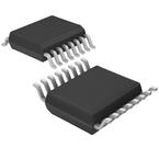
 器件3D模型
¥ 51.115
SN65LVDS22PW 数据手册 - TI(德州仪器)
制造商:
TI(德州仪器)
分类:
接口芯片
封装:
TSSOP-16
描述:
LVDS 收发器,Texas Instruments### LVDS 通信低压差分信号或 LVDS 是可以在廉价双绞线铜电缆上以极高速度运行的电子信号系统。应用:Firewire、SATA、SCSI
Pictures:
3D模型
符号图
焊盘图
引脚图
产品图
页面导航:
导航目录
SN65LVDS22PW数据手册
Page:
of 16 Go
若手册格式错乱,请下载阅览PDF原文件

www.ti.com
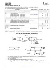
DIFFERENTIAL RECEIVER TO DRIVER SWITCHING CHARACTERISTICS
PARAMETER MEASUREMENT INFORMATION
Y
Z
V
OD
Input
(see Note A)
C
L
= 10 pF
(2 Places)
(see Note C)
R
L
(see Note B)
100%
80%
20%
0%
V
OD
0
t
f
t
r
V
I(B)
V
I(A)
1.4 V
1 V
A
Pulse
Generator
B
DE
SN65LVDS22
SN65LVDM22
SLLS315C – DECEMBER 1998 – REVISED JUNE 2002
over recommended operating conditions (unless otherwise noted)
PARAMETER TEST CONDITIONS MIN TYP
(1)
MAX UNIT
t
PLH
Differential propagation delay time, low-to-high 4 6 ns
t
PHL
Differential propagation delay time, high-to-low 4 6 ns
t
sk(p)
Pulse skew (|t
PHL
- t
PLH
|) 0.2 ns
t
r
Transition time, low-to-high SN65LVDS22 C
L
= 10 pF, See Figure 4 1 1.5 ns
t
r
Transition time, low-to-high SN65LVDM22 0.8 1.3 ns
t
f
Transition time, high-to-low SN65LVDS22 1 1.5 ns
t
f
Transition time, high-to-low SN65LVDM22 0.8 1.3 ns
t
PHZ
Propagation delay time, high-level-to-high-impedance output 4 10 ns
t
PLZ
Propagation delay time, low-level-to-high-impedance output 5 10 ns
See Figure 5
t
PZH
Propagation delay time, high-impedance-to-high-level output 5 10 ns
t
PZL
Propagation delay time, high-impedance-to-low-level output 6 10 ns
t
PHL_R1_Dx
0.2
t
PLH_R1_Dx
0.2
Channel-to-channel skew, receiver to driver
(2)
ns
t
PHL_R2_Dx
0.2
t
PLH_R2_Dx
0.2
f
max
Maximum operating frequency All channels switching 200 MHz
(1) All typical values are at 25°C and with a 3.3-V supply.
(2) These parametric values are measured over supply voltage and temperature ranges recommended for the device.
A. All input pulses are supplied by a generator having the following characteristics: t
r
or t
f
≤ 1 ns, pulse repetition rate
(PRR) = 50 Mpps, pulse width = 10 ±0.2 ns.
B. R
L
= 100 Ω or 50 Ω ±1%
C. C
L
includes instrumentation and fixture capacitance within 6 mm of the D.U.T.
Figure 2. Test Circuit and Voltage Definitions for the Differential Output Signal
6
Submit Documentation Feedback
器件 Datasheet 文档搜索
AiEMA 数据库涵盖高达 72,405,303 个元件的数据手册,每天更新 5,000 多个 PDF 文件
