Datasheet 搜索 > 逻辑控制器 > TI(德州仪器) > SN74LS07N 数据手册 > SN74LS07N 数据手册 6/21 页
 器件3D模型
¥ 1.568
SN74LS07N 数据手册 - TI(德州仪器)
制造商:
TI(德州仪器)
分类:
逻辑控制器
封装:
DIP-14
描述:
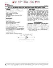
74LS 系列反相器和缓冲器,德州仪器德州仪器的 74LS 系列低功率肖特基逻辑集 IC 的一系列反相器和缓冲器。 74LS 系列使用双极接线技术,耦合了肖特基二极管夹,以实现与原始 74TTL 系列等同的工作速度,但是其功耗更低。### 74LS 系列
Pictures:
3D模型
符号图
焊盘图
引脚图
产品图
页面导航:
引脚图在P3Hot
典型应用电路图在P1P8P9
原理图在P7
封装尺寸在P12P14P15
标记信息在P12P13
封装信息在P11P12P13P14P15
技术参数、封装参数在P4
应用领域在P1
电气规格在P5
导航目录
SN74LS07N数据手册
Page:
of 21 Go
若手册格式错乱,请下载阅览PDF原文件
t
PHL
t
PLH
t
PLH
t
PHL
LOAD CIRCUIT
FOR 3-STATE OUTPUTS
High-Level
Pulse
Low-Level
Pulse
VOLTAGE WAVEFORMS
PULSE DURATIONS
Input
Out-of-Phase
Output
(see Note D)
3 V
0 V
V
OL
V
OH
V
OH
V
OL
In-Phase
Output
(see Note D)
VOLTAGE WAVEFORMS
PROPAGATION DELAY TIMES
V
CC
R
L
Test
Point
From Output
Under Test
C
L
(see Note A)
LOAD CIRCUIT
FOR OPEN-COLLECTOR OUTPUTS
LOAD CIRCUIT
FOR 2-STATE TOTEM-POLE OUTPUTS
(see Note B)
V
CC
R
L
From Output
Under Test
C
L
(see Note A)
Test
Point
(see Note B
)
V
CC
R
L
From Output
Under Test
C
L
(see Note A)
Test
Point
5 kΩ
S1
S2
t
PHZ
t
PLZ
t
PZL
t
PZH
3 V
3 V
0 V
0 V
t
h
t
su
VOLTAGE WAVEFORMS
SETUP AND HOLD TIMES
Timing
Input
Data
Input
3 V
0 V
Output
Control
(low-level
enabling)
Waveform 1
(see Notes C
and D)
Waveform 2
(see Notes C
and D)
≈1.5 V
V
OH
− 0.5 V
V
OL
+ 0.5 V
≈1.5 V
VOLTAGE WAVEFORMS
ENABLE AND DISABLE TIMES, 3-STATE OUTPUTS
1.3 V 1.3 V
1.3 V 1.3 V
1.3 V
1.3 V 1.3 V
1.3 V 1.3 V
1.3 V
1.3 V
t
w
1.3 V 1.3 V
1.3 V 1.3 V
1.3 V 1.3 V
V
OL
V
OH
6
SN74LS07
SDLS021D –MAY 1990–REVISED APRIL 2016
www.ti.com
Product Folder Links: SN74LS07
Submit Documentation Feedback Copyright © 1990–2016, Texas Instruments Incorporated
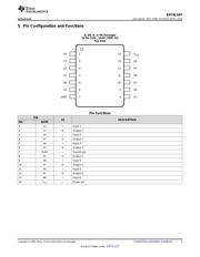
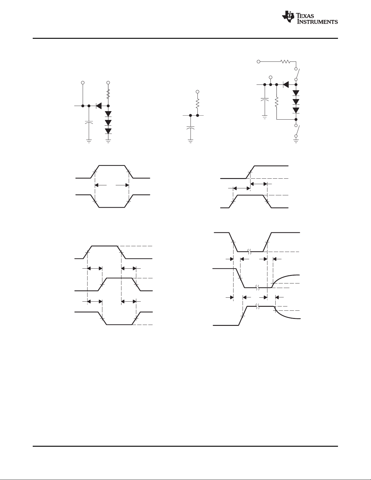
7 Parameter Measurement Information
A. C
L
includes probe and jig capacitance.
B. All diodes are 1N3064 or equivalent.
C. Waveform 1 is for an output with internal conditions such that the output is low, except when disabled by the output
control.
Waveform 2 is for an output with internal conditions such that the output is high, except when disabled by the output
control.
D. S1 and S2 are closed for t
PLH
, t
PHL
, t
PHZ
, and t
PLZ
; S1 is open and S2 is closed for t
PZH
; S1 is closed and S2 is open
for t
PZL
.
E. Phase relationships between inputs and outputs have been chosen arbitrarily for these examples.
F. All input pulses are supplied by generators having the following characteristics: PRR ≤ 1 MHz, Z
O
≈ 50 Ω, t
r
≤ 1.5 ns,
t
f
≤ 2.6 ns.
G. The outputs are measured one at a time, with one input transition per measurement.
Figure 2. Load Circuits and Voltage Waveforms
器件 Datasheet 文档搜索
AiEMA 数据库涵盖高达 72,405,303 个元件的数据手册,每天更新 5,000 多个 PDF 文件
