Datasheet 搜索 > 微控制器 > ST Microelectronics(意法半导体) > STM32F050C4T6TR 数据手册 > STM32F050C4T6TR 数据手册 74/97 页
 器件3D模型
¥ 10.499
STM32F050C4T6TR 数据手册 - ST Microelectronics(意法半导体)
制造商:
ST Microelectronics(意法半导体)
分类:
微控制器
封装:
LQFP
描述:
STM32F05 系列微处理器,STMicroelectronicsSTM32F05 微控制器系列 ARM Cortex™-M0 32 位 RISC 内核工作频率高达 48MHz,带高速闪存和一系列增强型外设,它们还包括 I²C、SPI、I²S 和 USART 通信接口、计时器、ADC 和 DAC。 ARM Cortex™-M0 STM32 F05,具有实时性能,可低功耗工作,能够在 STMicroelectronics STM32 平台上运行。 微控制器可用于如 HVAC、应用控制、消费者电器用具、PC 外设、手持设备及其他许多应用领域。Cortex™-M0:48MHz 频率 12 位 ADC;16 位计时器;32 位计时器和一个高级控制 PWM 计时器 温度范围:-40°C 至 +85°C 或 -40°C 至 +105°C 温度 电源:2V 至 3.6V **STM32F05**:闪存多达 32kB,SRAM 多达 4kB **STM32F051x4**、**STM32F051x6** 和 **STM32F051x8**:闪存多达 64kB,SRAM 多达 8kB ### STM32F0 系列 32 位 ARM® Cortex®-M0 微控制器,STMicroelectronicsSTM32 F0 系列 32 位闪存微控制器 (MCU) 基于 ARM Cortex™-M0 核心;为嵌入式应用特别开发的核心。 STMicroelectronics 的 STM32 ARM Cortex™ M 处理器得益于 Cortex-M0 体系结构增强功能,包括数字信号处理、实时性能、低电压和低功率。 ST ARM® STM32 F0 主流系列提供 32 位性能,且特别适用于小项目或平台决策,具有易于使用功能。展开
Pictures:
3D模型
符号图
焊盘图
引脚图
产品图
页面导航:
引脚图在P23P24P25P26P27P28P29P30P31P87Hot
典型应用电路图在P55P56P74
原理图在P11
封装尺寸在P84
型号编码规则在P93P94P95
封装信息在P84P85P86P87P88P89P90P91P92P93P94
技术参数、封装参数在P37
应用领域在P97
电气规格在P35P36P37P38P39P40P41P42P43P44P45P46
导航目录
STM32F050C4T6TR数据手册
Page:
of 97 Go
若手册格式错乱,请下载阅览PDF原文件

Electrical characteristics STM32F050xx
74/97 Doc ID 023683 Rev 1
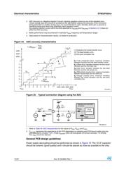
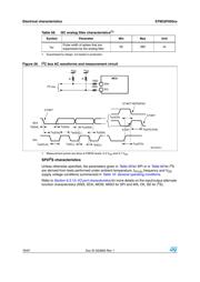
Figure 24. ADC accuracy characteristics
Figure 25. Typical connection diagram using the ADC
1. Refer to Table 49: ADC characteristics for the values of R
AIN
, R
ADC
and C
ADC
.
2. C
parasitic
represents the capacitance of the PCB (dependent on soldering and PCB layout quality) plus the
pad capacitance (roughly 7 pF). A high C
parasitic
value will downgrade conversion accuracy. To remedy
this, f
ADC
should be reduced.
General PCB design guidelines
Power supply decoupling should be performed as shown in Figure 10. The 10 nF capacitor
should be ceramic (good quality) and it should be placed as close as possible to the chip.
2. ADC Accuracy vs. Negative Injection Current: Injecting negative current on any of the standard (non-
robust) analog input pins should be avoided as this significantly reduces the accuracy of the conversion
being performed on another analog input. It is recommended to add a Schottky diode (pin to ground) to
standard analog pins which may potentially inject negative current.
Any positive injection current within the limits specified for I
INJ(PIN)
and ΣI
INJ(PIN)
in Section 6.3.13 does not
affect the ADC accuracy.
3. Better performance may be achieved in restricted V
DDA
, frequency and temperature ranges.
4. Data based on characterization results, not tested in production.
E
O
E
G
1LSB
IDEAL
(1) Example of an actual transfer curve
(2) The ideal transfer curve
(3) End point correlation line
E
T
=Total Unadjusted Error: maximum deviation
between the actual and the ideal transfer curves.
E
O
=Offset Error: deviation between the first actual
transition and the first ideal one.
E
G
=Gain Error: deviation between the last ideal
transition and the last actual one.
E
D
=Differential Linearity Error: maximum deviation
between actual steps and the ideal one.
E
L
=Integral Linearity Error: maximum deviation
between any actual transition and the end point
correlation line.
4095
4094
4093
5
4
3
2
1
0
7
6
1234567
4093 4094 4095 4096
(1)
(2)
E
T
E
D
E
L
(3)
V
DDA
V
SSA
-36
1LSB
IDEAL
V
DDA
-36
6
$$!
AINx
I
L
±1 μA
0.6 V
V
T
R
AIN
(1)
C
parasitic
V
AIN
0.6 V
V
T
R
ADC
12-bit
converter
C
ADC
Sample and hold ADC
converter
器件 Datasheet 文档搜索
AiEMA 数据库涵盖高达 72,405,303 个元件的数据手册,每天更新 5,000 多个 PDF 文件
