Datasheet 搜索 > 接口芯片 > TI(德州仪器) > TCA9535RTWR 数据手册 > TCA9535RTWR 数据手册 24/43 页

¥ 3.616
TCA9535RTWR 数据手册 - TI(德州仪器)
制造商:
TI(德州仪器)
分类:
接口芯片
封装:
WQFN-24
描述:
TEXAS INSTRUMENTS TCA9535RTWR 输入/输出扩展, 16bit, 400 kHz, I2C, SMBus, 1.65 V, 5.5 V, WQFN
Pictures:
3D模型
符号图
焊盘图
引脚图
产品图
页面导航:
引脚图在P3Hot
典型应用电路图在P24P25
原理图在P1P14P16
封装尺寸在P31P33P34
标记信息在P31
封装信息在P30P31P32P33P34
技术参数、封装参数在P4
应用领域在P1P24P43
电气规格在P5P6P14P25
导航目录
TCA9535RTWR数据手册
Page:
of 43 Go
若手册格式错乱,请下载阅览PDF原文件
P00
P01
P02
P03
P04
P05
A2
A1
A0
A
B
P06
P07
P10
P11
P12
P13
P14
P15
P16
P17
V
CC
V
CC
V
CC
(5 V)
Controlled Switch
(e.g., CBT Device)
GND
INT
SDA
SCL
INT
Subsystem 1
(e.g., Temperature
Sensor)
Subsystem 2
(e.g., Counter)
TCA9535
SDA
SCL
INT
GND
Keypad
ALARM
RESET
ENABLE
Subsystem 3
(e.g., Alarm)
Master
Controller
4
5
6
7
8
9
10
11
13
14
15
16
17
18
19
20
22
23
1
3
2
21
12
24
V
DD
100 kΩ
( 3)X
2 kΩ
10 kΩ
( 5)X
10 kΩ
( 4)X
TCA9535
SCPS201B –AUGUST 2009–REVISED AUGUST 2015
www.ti.com
9 Application and Implementation
NOTE
Information in the following applications sections is not part of the TI component
specification, and TI does not warrant its accuracy or completeness. TI’s customers are
responsible for determining suitability of components for their purposes. Customers should
validate and test their design implementation to confirm system functionality.
9.1 Application Information
Applications of the TCA9535 will have this device connected as a slave to an I
2
C master (processor), and the I
2
C
bus may contain any number of other slave devices. The TCA9535 will typically be in a remote location from the
master, placed close to the GPIOs to which the master needs to monitor or control.
IO Expanders such as the TCA9535 are typically used for controlling LEDs (for feedback or status lights),
controlling enable or reset signals of other devices, and even reading the outputs of other devices or buttons.
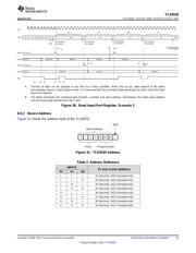
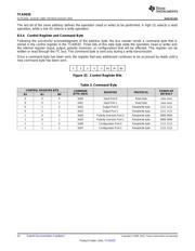
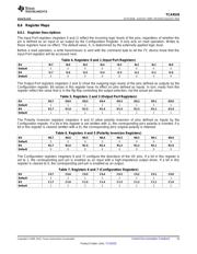
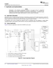
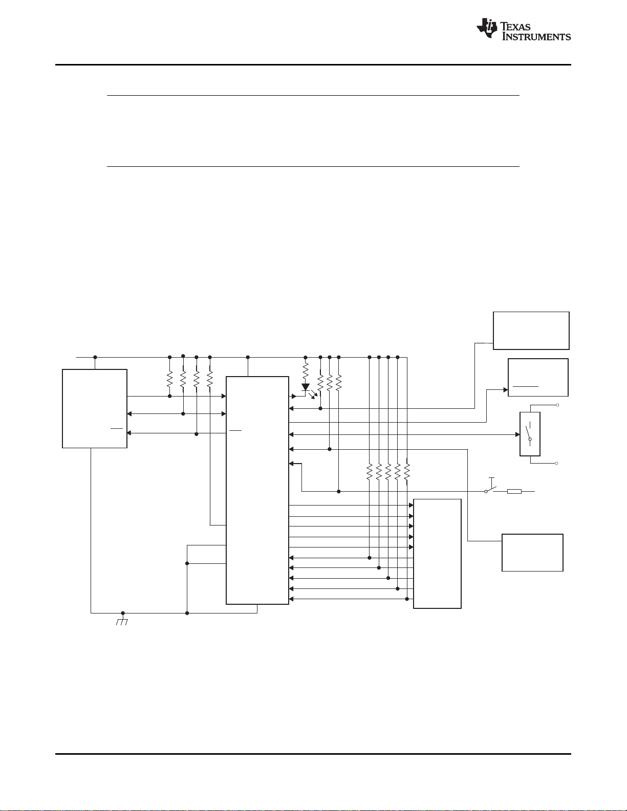
9.2 Typical Application
Figure 33 shows an application in which the TCA9535 can be used.
A. Device address is configured as 0100100 for this example.
B. P00, P02, and P03 are configured as outputs.
C. P01, P04–P07, and P10–P17 are configured as inputs.
D. Pin numbers shown are for the PW package.
Figure 33. Typical Application Diagram
24 Submit Documentation Feedback Copyright © 2009–2015, Texas Instruments Incorporated
Product Folder Links: TCA9535
器件 Datasheet 文档搜索
AiEMA 数据库涵盖高达 72,405,303 个元件的数据手册,每天更新 5,000 多个 PDF 文件
