Datasheet 搜索 > 电压基准芯片 > TI(德州仪器) > TL4050A50QDCKRQ1 数据手册 > TL4050A50QDCKRQ1 数据手册 3/22 页

 器件3D模型
¥ 3.967
TL4050A50QDCKRQ1 数据手册 - TI(德州仪器)
制造商:
TI(德州仪器)
分类:
电压基准芯片
封装:
SC-70-5
描述:
固定电压、0.1%、50ppm/°C 汽车类精密微功耗并联电压基准 5-SC70 -40 to 125
Pictures:
3D模型
符号图
焊盘图
引脚图
产品图
页面导航:
引脚图在P10Hot
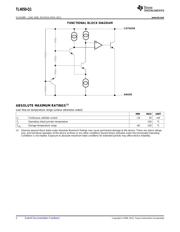
原理图在P2
封装尺寸在P1P12P14P15P17
焊盘布局在P18
型号编码规则在P1
标记信息在P12P13
封装信息在P1P12P13P14P15
技术参数、封装参数在P2
应用领域在P1
电气规格在P4P5P6P7
导航目录
TL4050A50QDCKRQ1数据手册
Page:
of 22 Go
若手册格式错乱,请下载阅览PDF原文件
TL4050-Q1
www.ti.com
SLOS588F –JUNE 2008–REVISED APRIL 2013
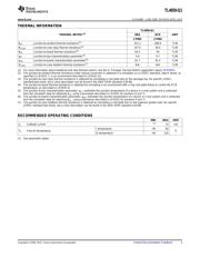
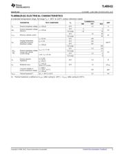
THERMAL INFORMATION
TL4050-Q1
THERMAL METRIC
(1)
DBZ DCK UNIT
3 PINS 5 PINS
θ
JA
Junction-to-ambient thermal resistance
(2)
331.1 289.9 °C/W
θ
JCtop
Junction-to-case (top) thermal resistance
(3)
107.5 56.4 °C/W
θ
JB
Junction-to-board thermal resistance
(4)
63.4 93 °C/W
ψ
JT
Junction-to-top characterization parameter
(5)
4.9 0.7 °C/W
ψ
JB
Junction-to-board characterization parameter
(6)
61.7 91.4 °C/W
θ
JCbot
Junction-to-case (bottom) thermal resistance
(7)
N/A N/A °C/W
(1) For more information about traditional and new thermal metrics, see the IC Package Thermal Metrics application report, SPRA953.
(2) The junction-to-ambient thermal resistance under natural convection is obtained in a simulation on a JEDEC-standard, high-K board, as
specified in JESD51-7, in an environment described in JESD51-2a.
(3) The junction-to-case (top) thermal resistance is obtained by simulating a cold plate test on the package top. No specific JEDEC-
standard test exists, but a close description can be found in the ANSI SEMI standard G30-88.
(4) The junction-to-board thermal resistance is obtained by simulating in an environment with a ring cold plate fixture to control the PCB
temperature, as described in JESD51-8.
(5) The junction-to-top characterization parameter, ψ
JT
, estimates the junction temperature of a device in a real system and is extracted
from the simulation data for obtaining θ
JA
, using a procedure described in JESD51-2a (sections 6 and 7).
(6) The junction-to-board characterization parameter, ψ
JB
, estimates the junction temperature of a device in a real system and is extracted
from the simulation data for obtaining θ
JA
, using a procedure described in JESD51-2a (sections 6 and 7).
(7) The junction-to-case (bottom) thermal resistance is obtained by simulating a cold plate test on the exposed (power) pad. No specific
JEDEC standard test exists, but a close description can be found in the ANSI SEMI standard G30-88.
Spacer
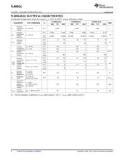
RECOMMENDED OPERATING CONDITIONS
MIN MAX UNIT
I
Z
Cathode current
(1)
15 mA
I temperature –40 85
T
A
Free-air temperature °C
Q temperature –40 125
(1) See parametric tables
Copyright © 2008–2013, Texas Instruments Incorporated Submit Documentation Feedback 3
器件 Datasheet 文档搜索
AiEMA 数据库涵盖高达 72,405,303 个元件的数据手册,每天更新 5,000 多个 PDF 文件
