Datasheet 搜索 > 电压基准芯片 > TI(德州仪器) > TL431AQDBZRQ1 数据手册 > TL431AQDBZRQ1 数据手册 4/26 页

¥ 0.567
TL431AQDBZRQ1 数据手册 - TI(德州仪器)
制造商:
TI(德州仪器)
分类:
电压基准芯片
封装:
SOT-23-3
描述:
可调式精密并联稳压器 ADJUSTABLE PRECISION SHUNT REGULATOR
Pictures:
3D模型
符号图
焊盘图
引脚图
产品图
页面导航:
导航目录
TL431AQDBZRQ1数据手册
Page:
of 26 Go
若手册格式错乱,请下载阅览PDF原文件
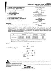
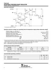
TL431−Q1
ADJUSTABLE PRECISION SHUNT REGULATOR
SGLS302D − MARCH 2005 − REVISED MARCH 2013
4
POST OFFICE BOX 655303 • DALLAS, TEXAS 75265
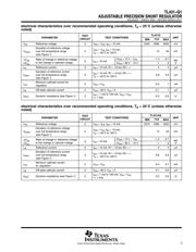
electrical characteristics over recommended operating conditions, T
A
= 25°C (unless otherwise
noted)
PARAMETER
TEST
TEST CONDITIONS
TL431BQ
UNIT
PARAMETER
TEST
CIRCUIT
TEST CONDITIONS
MIN TYP MAX
UNIT
V
ref
Reference voltage 2 V
KA
= V
ref
, I
KA
= 10 mA 2483 2495 2507 mV
V
I(dev)
Deviation of reference voltage
over full temperature range
(see Figure 1)
2
V
KA
= V
ref,
I
KA
= 10 mA,
T
A
= −40°C to 125°C
14 34 mV
DV
ref
Ratio of chan
g
e in reference volta
g
e
3
I 10 mA
ΔV
KA
= 10 V − V
ref
−1.4 −2.7
mV
DV
re
f
DV
KA
Ratio of change in reference voltage
to the change in cathode voltage
3 I
KA
= 10 mA
ΔV
KA
= 36 V − 10 V −1 −2
m
V
V
I
ref
Reference current 3 I
KA
= 10 mA, R1 = 10 kΩ, R2 = ∞ 2 4 μA
I
I(dev)
Deviation of reference current
over full temperature range
(see Figure 1)
3
I
KA
= 10 mA, R1 = 10 kΩ, R2 = ∞,
T
A
= −40°C to 125°C
0.8 2.5 μA
I
min
Minimum cathode current
for regulation
2 V
KA
= V
ref
0.4 0.7 mA
I
off
Off-state cathode current 4 V
KA
= 36 V, V
ref
= 0 0.1 0.5 μA
|z
KA
| Dynamic impedance (see Figure 1) 1
I
KA
= 1 mA to 100 mA, V
KA
= V
ref
,
f ≤ 1 kHz
0.2 0.5 Ω
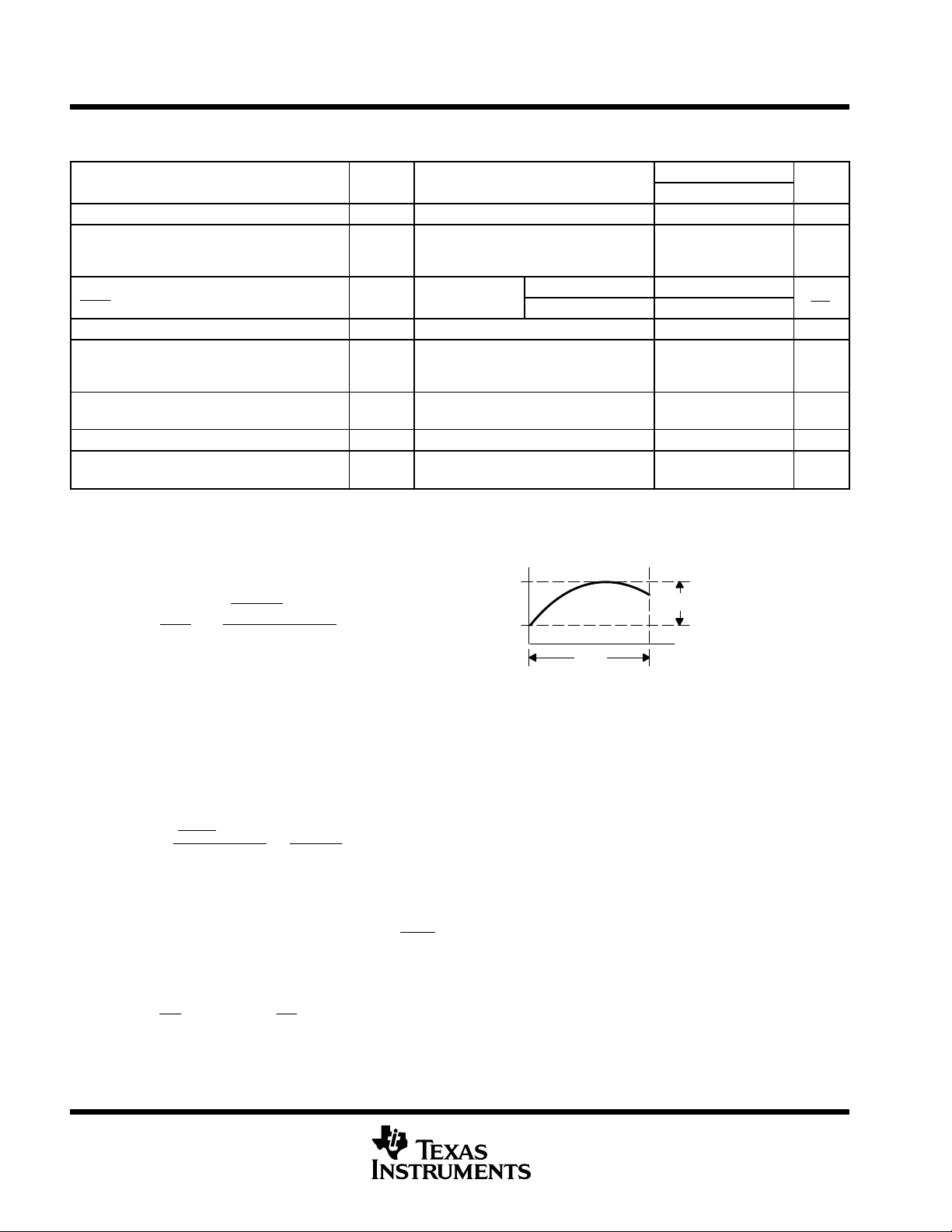
The deviation parameters, V
ref(dev)
and I
ref(dev)
, are defined as the differences between the maximum and minimum
values obtained over the recommended temperature range. The average full-range temperature coefficient of the
reference voltage, α
Vref
, is defined as:
where:
ΔT
A
is the recommended operating free-air temperature range of the device.
can be positive or negative, depending on whether minimum V
ref
or maximum V
ref
, respectively, occurs at the
lower temperature.
Example: maximum V
ref
= 2496 mV at 30°C, minimum V
ref
= 2492 mV at 0°C, V
ref
= 2495 mV at 25°C,
ΔT
A
= 70°C for TL431
Because minimum V
ref
occurs at the lower temperature, the coefficient is positive.
Calculating Dynamic Impedance
The dynamic impedance is defined as:
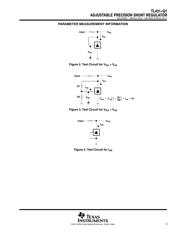
When the device is operating with two external resistors (see Figure 3), the total dynamic impedance of the circuit
is given by:
Maximum V
ref
Minimum V
ref
ΔT
A
V
I(dev)
Ť
a
V
ref
Ť
ǒ
ppm
°C
Ǔ
+
ǒ
V
I
(
dev
)
V
ref
at 25°C
Ǔ
10
6
DT
A
Ť
a
V
ref
Ť
+
ǒ
4mV
2495 mV
Ǔ
10
6
70°C
[
23 ppm
°C
|
z
KA
|
+
DV
KA
DI
KA
|
zȀ
|
+
DV
DI
[
|
z
KA
|
ǒ
1 )
R1
R2
Ǔ
a
V
ref
Figure 1. Calculating Deviation Parameters and Dynamic Impedance
器件 Datasheet 文档搜索
AiEMA 数据库涵盖高达 72,405,303 个元件的数据手册,每天更新 5,000 多个 PDF 文件
