Datasheet 搜索 > 电压基准芯片 > ON Semiconductor(安森美) > TL431CDR2G 数据手册 > TL431CDR2G 数据手册 2/20 页
 器件3D模型
¥ 1.265
TL431CDR2G 数据手册 - ON Semiconductor(安森美)
制造商:
ON Semiconductor(安森美)
分类:
电压基准芯片
封装:
SOIC-8
描述:
ON Semiconductor### 电压参考,ON Semiconductor
Pictures:
3D模型
符号图
焊盘图
引脚图
产品图
页面导航:
典型应用电路图在P7
原理图在P2
封装尺寸在P17P18P19P20
焊盘布局在P19P20
型号编码规则在P1P13P14P15P16P20
标记信息在P1P16
封装信息在P13P14P15P16
技术参数、封装参数在P13P14P15P16
应用领域在P7P11
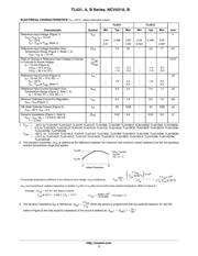
电气规格在P3P4
导航目录
TL431CDR2G数据手册
Page:
of 20 Go
若手册格式错乱,请下载阅览PDF原文件
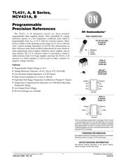
TL431, A, B Series, NCV431A, B
http://onsemi.com
2
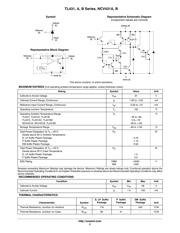
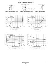
Representative Block Diagram
1.0 k
Cathode
(K)
2.5 V
ref
Anode (A)
Reference
(R)
4.0 k
150
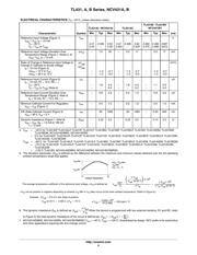
Symbol
10 k
20 pF
800
Cathode (K)
3.28 k
Representative Schematic Diagram
Component values are nominal
Anode (A)
-
+
Anode
(A)
800
Reference
(R)
2.4 k 7.2 k
20 pF
800
Cathode
(K)
Reference
(R)
This device contains 12 active transistors.
MAXIMUM RATINGS (Full operating ambient temperature range applies, unless otherwise noted.)
Rating
Symbol Value Unit
Cathode to Anode Voltage V
KA
37 V
Cathode Current Range, Continuous I
K
-100 to +150 mA
Reference Input Current Range, Continuous I
ref
-0.05 to +10 mA
Operating Junction Temperature T
J
150 °C
Operating Ambient Temperature Range
T
A
°C
TL431I, TL431AI, TL431BI -40 to +85
TL431C, TL431AC, TL431BC 0 to +70
NCV431AI, NCV431B, TL431BV -40 to +125
Storage Temperature Range T
stg
-65 to +150 °C
Total Power Dissipation @ T
A
= 25°C P
D
W
Derate above 25°C Ambient Temperature
D, LP Suffix Plastic Package 0.70
P Suffix Plastic Package 1.10
DM Suffix Plastic Package 0.52
Total Power Dissipation @ T
C
= 25°C P
D
W
Derate above 25°C Case Temperature
D, LP Suffix Plastic Package 1.5
P Suffix Plastic Package 3.0
ESD Rating HBM
MM
>2000
>200
V
Stresses exceeding Maximum Ratings may damage the device. Maximum Ratings are stress ratings only. Functional operation above the
Recommended Operating Conditions is not implied. Extended exposure to stresses above the Recommended Operating Conditions may affect
device reliability.
RECOMMENDED OPERATING CONDITIONS
Condition Symbol Min Max Unit
Cathode to Anode Voltage V
KA
V
ref
36 V
Cathode Current I
K
1.0 100 mA
THERMAL CHARACTERISTICS
Characteristic Symbol
D, LP Suffix
Package
P Suffix
Package
DM Suffix
Package
Unit
Thermal Resistance, Junction-to-Ambient
R
q
JA
178 114 240 °C/W
Thermal Resistance, Junction-to-Case
R
q
JC
83 41 - °C/W
器件 Datasheet 文档搜索
AiEMA 数据库涵盖高达 72,405,303 个元件的数据手册,每天更新 5,000 多个 PDF 文件
