Datasheet 搜索 > LED驱动器 > TI(德州仪器) > TLC59116IPWR 数据手册 > TLC59116IPWR 数据手册 15/39 页
 器件3D模型
¥ 4.386
TLC59116IPWR 数据手册 - TI(德州仪器)
制造商:
TI(德州仪器)
分类:
LED驱动器
封装:
TSSOP-28
描述:
TEXAS INSTRUMENTS TLC59116IPWR 芯片, 发光二极管驱动器, 恒流, TSSOP28, 整卷
Pictures:
3D模型
符号图
焊盘图
引脚图
产品图
页面导航:
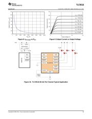
典型应用电路图在P13
原理图在P2
封装尺寸在P2P29P31P32
型号编码规则在P1P2
标记信息在P2P29
封装信息在P2P29P30P31P32
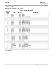
功能描述在P10
技术参数、封装参数在P5
应用领域在P39
电气规格在P6
导航目录
TLC59116IPWR数据手册
Page:
of 39 Go
若手册格式错乱,请下载阅览PDF原文件
TLC59116
www.ti.com
SLDS157D –FEBRUARY 2008–REVISED JULY 2011
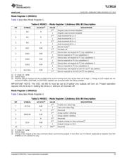
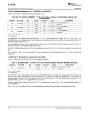
Mode Register 1 (MODE1)
Table 4 describes Mode Register 1.
Table 4. MODE1 – Mode Register 1 (Address 00h) Bit Description
BIT SYMBOL ACCESS
(1)
VALUE DESCRIPTION
0
(2)
Register auto-increment disabled
7 AI2 R
1 Register auto-increment enabled
0
(2)
Auto-increment bit 1 = 0
6 AI1 R
1 Auto-increment bit 1 = 1
0
(2)
Auto-increment bit 0 = 0
5 AI0 R
1 Auto-increment bit 0 = 1
0 Normal mode
(3)
4 OSC R/W
1
(2)
Oscillator off.
0
(2)
Device does not respond to I
2
C bus subaddress 1.
3 SUB1 R/W
1 Device responds to I
2
C bus subaddress 1.
0
(2)
Device does not respond to I
2
C bus subaddress 2.
2 SUB2 R/W
1 Device responds to I
2
C bus subaddress 2.
0
(2)
Device does not respond to I
2
C bus subaddress 3.
1 SUB3 R/W
1 Device responds to I
2
C bus subaddress 3.
0 Device does not respond to LED All Call I
2
C bus address.
0 ALLCALL R/W
1
(2)
Device responds to LED All Call I
2
C bus address.
(1) R = read, W = write
(2) Default value
(3) Requires 500 μs maximum for the oscillator to be up and running once OSC bit has been set to logic 1. Timings on LED outputs are not
ensured if PWMx, GRPPWM, or GRPFREQ registers are accessed within the 500-μs window.
IMPORTANT NOTE: The OSC bit (Bit 4) must be set to 0 before any outputs will turn on. Proper operation
requires this bit to be 0. Setting the bit to a 1 will turn all channels off.
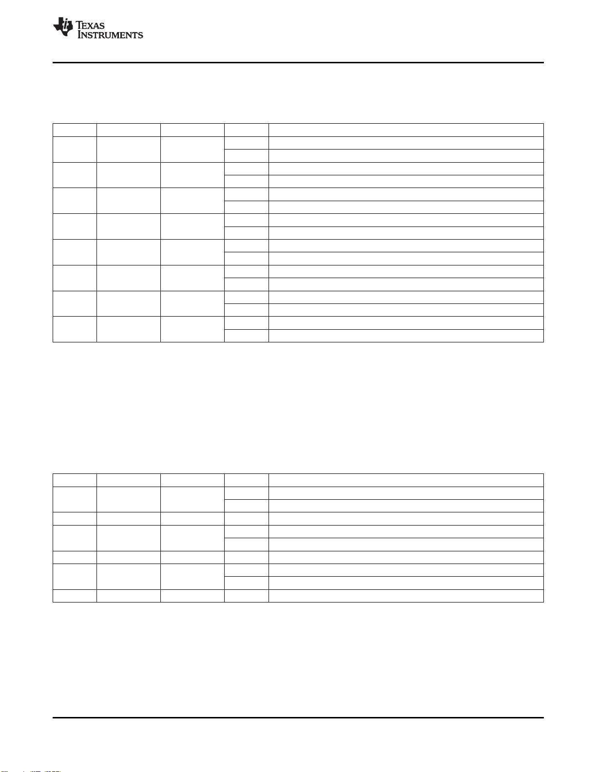
Mode Register 2 (MODE2)
Table 5 describes Mode Register 2.
Table 5. MODE2 – Mode Register 2 (Address 01h) Bit Description
BIT SYMBOL ACCESS
(1)
VALUE DESCRIPTION
0
(2)
Enable error status flag
7 EFCLR R/W
1 Clear error status flag
6 R 0
(2)
Reserved
0
(2)
Group control = dimming
5 DMBLNK R/W
1 Group control = blinking
4 R 0
(2)
Reserved
0
(2)
Outputs change on Stop command
(3)
3 OCH R/W
1 Outputs change on ACK
2:0 R 000
(2)
Reserved
(1) R = read, W = write
(2) Default value
(3) Change of the outputs at the Stop command allows synchronizing outputs of more than one TLC59116. Applicable to registers from 02h
(PWM0) to 17h (LEDOUT3) only.
Copyright © 2008–2011, Texas Instruments Incorporated 15
器件 Datasheet 文档搜索
AiEMA 数据库涵盖高达 72,405,303 个元件的数据手册,每天更新 5,000 多个 PDF 文件
