Datasheet 搜索 > LED驱动器 > TI(德州仪器) > TLC5947RHBTG4 数据手册 > TLC5947RHBTG4 数据手册 6/33 页
 器件3D模型
¥ 53.695
TLC5947RHBTG4 数据手册 - TI(德州仪器)
制造商:
TI(德州仪器)
分类:
LED驱动器
封装:
VQFN-32
描述:
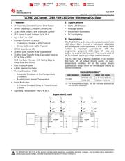
24通道,12位PWM LED驱动器,内部振荡器 24-Channel, 12-Bit PWM LED Driver with Internal Oscillator
Pictures:
3D模型
符号图
焊盘图
引脚图
产品图
页面导航:
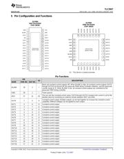
引脚图在P3P4Hot
典型应用电路图在P18
原理图在P11P12P20
封装尺寸在P23P25P26
标记信息在P23P24
封装信息在P22P23P24P25P26
技术参数、封装参数在P4
应用领域在P1P33
电气规格在P6
导航目录
TLC5947RHBTG4数据手册
Page:
of 33 Go
若手册格式错乱,请下载阅览PDF原文件
100
3V 1V-
´
(I atV =1V)
OUTn OUTn
(I atV =3V) (I atV =1V)-
OUTn OUTn OUTn OUTn
D (%/V)=
100
(I atV =3.0V)
OUTn CC
(I atV =5.5V) (I atV =3.0V)
OUTn CC OUTn CC
-
5.5V 3V-
D (%/V)=
´
I =41 ´
OUT(IDEAL)
1.20
R
IREF
D (%)=
IdealOutputCurrent
- (IdealOutputCurrent)
(I +I +...I +I )
OUT0 OUT1 OUT22 OUT23
24
´ 100
D (%)=
I
OUTn
- 1
(I +I +...+I )
OUT0 OUT1 OUT22
+I
OUT23
24
´ 100
.
Ideal current is calculated by the formula:
TLC5947
SBVS114B –JULY 2008–REVISED JANUARY 2015
www.ti.com
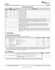
6.6 Electrical Characteristics
At V
CC
= 3.0 V to 5.5 V and T
A
= –40°C to 85° C. Typical values at V
CC
= 3.3 V and T
A
= 25°C, unless otherwise noted.
PARAMETER TEST CONDITIONS MIN TYP MAX UNIT
V
OH
High-level output voltage I
OH
= –3 mA at SOUT V
CC
– 0.4 V
CC
V
V
OL
Low-level output voltage I
OL
= 3 mA at SOUT 0.4 V
I
IN
Input current V
IN
= V
CC
or GND at SIN, XLAT, and BLANK –1 1 μA
SIN/SCLK/XLAT = low, BLANK = high, V
OUTn
= 1 V,
I
CC1
0.5 3 mA
R
IREF
= 24 kΩ
SIN/SCLK/XLAT = low, BLANK = high, V
OUTn
= 1 V,
I
CC2
1 6 mA
R
IREF
= 3.3 kΩ
Supply current (V
CC
)
SIN/SCLK/XLAT = low, BLANK = low, V
OUTn
= 1 V,
I
CC3
15 45 mA
R
IREF
= 3.3 kΩ, GSn = FFFh
SIN/SCLK/XLAT = low, BLANK = low, V
OUTn
= 1 V,
I
CC4
30 90 mA
R
IREF
= 1.6 kΩ, GSn = FFFh
All OUTn = ON, V
OUTn
= 1 V, V
OUTfix
= 1 V,
I
OLC
Constant output current 27.7 30.75 33.8 mA
R
IREF
= 1.6 kΩ
BLANK = high, V
OUTn
= 30 V, R
IREF
= 1.6 kΩ,
I
OLK
Output leakage current 0.1 μA
At OUT0 to OUT23
Constant-current error All OUTn = ON, V
OUTn
= 1 V, V
OUTfix
= 1 V,
ΔI
OLC
–4% ±2% 4%
(channel-to-channel)
(1)
R
IREF
= 1.6 kΩ, At OUT0 to OUT23
Constant-current error All OUTn = ON, V
OUTn
= 1 V, V
OUTfix
= 1 V,
ΔI
OLC1
–7% ±2% 7%
(device-to-device)
(2)
R
IREF
= 1.6 kΩ
All OUTn = ON, V
OUTn
= 1 V, V
OUTfix
= 1 V,
ΔI
OLC2
Line regulation
(3)
±1 ±3 %/V
R
IREF
= 1.6 kΩ, At OUT0 to OUT23
All OUTn = ON, V
OUTn
= 1 V to 3 V, V
OUTfix
= 1 V,
ΔI
OLC3
Load regulation
(4)
±2 ±6 %/V
R
IREF
= 1.6 kΩ, At OUT0 to OUT23
T
DOWN
Thermal shutdown threshold Junction temperature
(5)
150 162 175 °C
T
HYS
Thermal error hysteresis Junction temperature
(5)
5 10 20 °C
V
IREF
Reference voltage output R
IREF
= 1.6 kΩ 1.16 1.20 1.24 V
(1) The deviation of each output from the average of OUT0–OUT23 constant-current. Deviation is calculated by the formula:
(2) The deviation of the OUT0–OUT23 constant-current average from the ideal constant-current value. Deviation is calculated by the
following formula:
(3) Line regulation is calculated by this equation:
(4) Load regulation is calculated by the equation:
(5) Not tested. Specified by design.
6 Submit Documentation Feedback Copyright © 2008–2015, Texas Instruments Incorporated
Product Folder Links: TLC5947
器件 Datasheet 文档搜索
AiEMA 数据库涵盖高达 72,405,303 个元件的数据手册,每天更新 5,000 多个 PDF 文件
