Datasheet 搜索 > 运算放大器 > TI(德州仪器) > TLV2774CPW 数据手册 > TLV2774CPW 数据手册 5/74 页
 器件3D模型
¥ 30.835
TLV2774CPW 数据手册 - TI(德州仪器)
制造商:
TI(德州仪器)
分类:
运算放大器
封装:
TSSOP-14
描述:
低电压高速 CMOS 运算放大器### 运算放大器,Texas Instruments
Pictures:
3D模型
符号图
焊盘图
引脚图
产品图
页面导航:
原理图在P36
封装尺寸在P3P4P42P43P44P45P46P47P50P51P52P69
焊盘布局在P70
标记信息在P42P43P44P45P46P47P48
封装信息在P42P43P44P45P46P47P48P49P50P51P52
应用领域在P1P49P74
型号编号列表在P3
导航目录
TLV2774CPW数据手册
Page:
of 74 Go
若手册格式错乱,请下载阅览PDF原文件
SLOS209G − JANUARY 1998 − REVISED FEBRUARY 2004
5
WWW.TI.COM
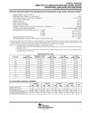
absolute maximum ratings over operating free-air temperature range (unless otherwise noted)
†
Supply voltage, V
DD
(see Note 1) 7 V. . . . . . . . . . . . . . . . . . . . . . . . . . . . . . . . . . . . . . . . . . . . . . . . . . . . . . . . . . . . .
Differential input voltage, V
ID
(see Note 2) ±V
DD
. . . . . . . . . . . . . . . . . . . . . . . . . . . . . . . . . . . . . . . . . . . . . . . . . . .
Input voltage range, V
I
(any input, see Note 1) −0.3 V to V
DD
. . . . . . . . . . . . . . . . . . . . . . . . . . . . . . . . . . . . . . . .
Input current, I
I
(any input) ±4 mA. . . . . . . . . . . . . . . . . . . . . . . . . . . . . . . . . . . . . . . . . . . . . . . . . . . . . . . . . . . . . . . .
Output current, I
O
±50 mA. . . . . . . . . . . . . . . . . . . . . . . . . . . . . . . . . . . . . . . . . . . . . . . . . . . . . . . . . . . . . . . . . . . . . . .
Total current into V
DD+
±50 mA. . . . . . . . . . . . . . . . . . . . . . . . . . . . . . . . . . . . . . . . . . . . . . . . . . . . . . . . . . . . . . . . . .
Total current out of GND ±50 mA. . . . . . . . . . . . . . . . . . . . . . . . . . . . . . . . . . . . . . . . . . . . . . . . . . . . . . . . . . . . . . . .
Duration of short-circuit current (at or below) 25°C (see Note 3) unlimited. . . . . . . . . . . . . . . . . . . . . . . . . . . . . .
Continuous total power dissipation See Dissipation Rating Table. . . . . . . . . . . . . . . . . . . . . . . . . . . . . . . . . . . . .
Operating free-air temperature range, T
A
: C suffix 0°C to 70°C. . . . . . . . . . . . . . . . . . . . . . . . . . . . . . . . . . . . . .
I suffix −40°C to 125°C. . . . . . . . . . . . . . . . . . . . . . . . . . . . . . . . . . . .
Q suffix −40°C to 125°C. . . . . . . . . . . . . . . . . . . . . . . . . . . . . . . . . . .
M suffix −55°C to 125°C. . . . . . . . . . . . . . . . . . . . . . . . . . . . . . . . . .
Storage temperature range, T
stg
−65°C to 150°C. . . . . . . . . . . . . . . . . . . . . . . . . . . . . . . . . . . . . . . . . . . . . . . . . . .
Lead temperature 1,6 mm (1/16 inch) from case for 10 seconds 260°C. . . . . . . . . . . . . . . . . . . . . . . . . . . . . . .
†
Stresses beyond those listed under “absolute maximum ratings” may cause permanent damage to the device. These are stress ratings only, and
functional operation of the device at these or any other conditions beyond those indicated under “recommended operating conditions” is not
implied. Exposure to absolute-maximum-rated conditions for extended periods may affect device reliability.
NOTES: 1. All voltage values, except differential voltages, are with respect to GND.
2. Differential voltages are at the noninverting input with respect to the inverting input. Excessive current flows when input is brought
below GND − 0.3 V.
3. The output may be shorted to either supply. Temperature and/or supply voltages must be limited to ensure that the maximum
dissipation rating is not exceeded.
DISSIPATION RATING TABLE
PACKAGE
T
A
≤
25
°
C
DERATING FACTOR
T
A
= 70
°
C
T
A
= 85
°
C
T
A
= 125
°
C
PACKAGE
T
A
≤ 25 C
POWER RATING
DERATING FACTOR
ABOVE T
A
= 25°C
T
A
= 70 C
POWER RATING
T
A
= 85 C
POWER RATING
T
A
= 125 C
POWER RATING
D 725 mW 5.8 mW/°C 464 mW 377 mW 145 mW
DBV 437 mW 3.5 mW/°C 280 mW 227 mW 87 mW
DGK 424 mW 3.4 mW/°C 271 mW 220 mW 85 mW
DGS 424 mW 3.4 mW/°C 271 mW 220 mW 85 mW
FK 1375 mW 11.0 mW/°C 672 mW 546 mW 210 mW
JG 1050 mW 8.4 mW/°C 880 mW 714 mW 275 mW
N 1150 mW 9.2 mW/°C 736 mW 598 mW 230 mW
P 1000 mW 8.0 mW/°C 640 mW 520 mW 200 mW
PW 700 mW 5.6 mW/°C 448 mW 364 mW 140 mW
U 675 mW 5.4 mW/°C 432 mW 350 mW 135 mW
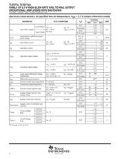
recommended operating conditions
C SUFFIX I SUFFIX Q SUFFIX M SUFFIX
UNIT
MIN MAX MIN MAX MIN MAX MIN MAX
UNIT
Supply voltage, V
DD
2.5 6 2.5 6 2.5 6 2.5 6 V
Input voltage range, V
I
GND V
DD+
−1.3 GND V
DD+
−1.3 GND V
DD+
−1.3 GND V
DD+
−1.3 V
Common-mode input voltage, V
IC
GND V
DD+
−1.3 GND V
DD+
−1.3 GND V
DD+
−1.3 GND V
DD+
−1.3 V
Operating free-air temperature, T
A
0 70 −40 125 −40 125 −55 125 °C
器件 Datasheet 文档搜索
AiEMA 数据库涵盖高达 72,405,303 个元件的数据手册,每天更新 5,000 多个 PDF 文件
