Datasheet 搜索 > 可编程定时器芯片 > ST Microelectronics(意法半导体) > TS556CD 数据手册 > TS556CD 数据手册 14/19 页
 器件3D模型
¥ 2.751
TS556CD 数据手册 - ST Microelectronics(意法半导体)
制造商:
ST Microelectronics(意法半导体)
分类:
可编程定时器芯片
封装:
SOIC-14
描述:
低功率双路CMOS定时器 LOW POWER DUAL CMOS TIMERS
Pictures:
3D模型
符号图
焊盘图
引脚图
产品图
页面导航:
引脚图在P1Hot
原理图在P4P5
封装尺寸在P15P16
型号编码规则在P17
标记信息在P17
封装信息在P17
技术参数、封装参数在P3
应用领域在P13P14
电气规格在P6P7P8P9P10P11P12
导航目录
TS556CD数据手册
Page:
of 19 Go
若手册格式错乱,请下载阅览PDF原文件
Application information TS556
14/19 DocID4078 Rev 3
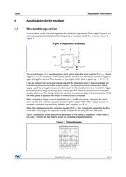
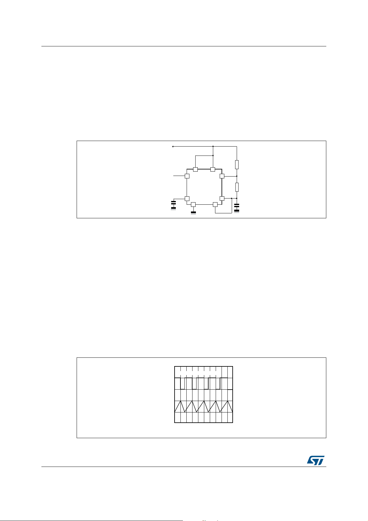
4.2 Astable operation
When the circuit is connected as shown in Figure 6 (pins 2 and 6 connected) it triggers itself
and runs as a multivibrator. The external capacitor charges through R
A
and R
B
and
discharges through R
B
only. Thus the duty cycle may be precisely set by the ratio of these
two resistors.
In the astable mode of operation, C charges and discharges between 1/3 V
CC
and 2/3 V
CC
.
As in the triggered mode, the charge and discharge times and therefore frequency, are
independent of the supply voltage.
Figure 6. Application schematic
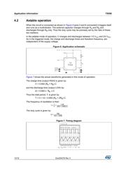
Figure 7 shows the actual waveforms generated in this mode of operation.
The charge time (output HIGH) is given by:
t1 = 0.693 (R
A
+ R
B
) C
and the discharge time (output LOW) by:
t2 = 0.693 x R
B
x C
Thus the total period, T, is given by:
T = t1 + t2 = 0.693 (R
A
+ 2R
B
) C
The frequency of oscillation is then:
The duty cycle is given by:
Figure 7. Timing diagram
V
CC
Reset
Out
R
C
R
A
B
Control
Voltage
0.01 F
1/2
TS556
f =
1
T
--- =
1.44
(RA 2RB)C+
--------------------------------------
D =
RB
RA 2RB+
---------------------------
t = 0.5 ms / div
OUTPUT VOLTAGE = 5.0V/div
CAPACITOR VOLTAGE = 1.0V/div
L
R = R = 4.8 k , C = 0.1 F , R = 1.0k
AB
器件 Datasheet 文档搜索
AiEMA 数据库涵盖高达 72,405,303 个元件的数据手册,每天更新 5,000 多个 PDF 文件
