Datasheet 搜索 > 可调电容 > muRata(村田) > TZB4Z100AB10R01 数据手册 > TZB4Z100AB10R01 数据手册 27/32 页

¥ 1.692
TZB4Z100AB10R01 数据手册 - muRata(村田)
制造商:
muRata(村田)
分类:
可调电容
封装:
100
Pictures:
3D模型
符号图
焊盘图
引脚图
产品图
页面导航:

导航目录
TZB4Z100AB10R01数据手册
Page:
of 32 Go
若手册格式错乱,请下载阅览PDF原文件

Notice (Soldering and Mounting)
Notice (Handling)
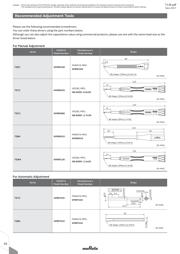
1. Use suitable screwdrivers that fit comfortably in
driver slot.
(1) Recommended screwdriver for manual adjustment
MURATA: KMDR010
(2) Recommended screwdriver bit for automatic
adjustment
MURATA: KMBT010
2. When adjusting with a screwdriver, do not apply
excessive force (preferably 1.0 N [Ref: 100gf] max.)
to minimize capacitance drift. Excessive force applied
to the screwdriver slot may cause deformation of the
products.
3. Do not apply adhesive, lock paints, or any other
substances to the trimmer capacitor to secure the
rotor position. They may cause corrosion or
electrical contact problems.
4. Do not break the cover film before the completion
of PCB mounting, soldering, and cleaning.
5. Do not clean the trimmer capacitor after the cover
film has been broken.
6. To break the cover film, first turn the screwdriver
more than 360°, and set the capacitance value.
(Inserting the screwdriver only will not break the
cover film.)
Notice (Other)
Before using trimmer capacitors, please test after
assembly in your particular mass production system.
T13E.pdf
Sep.1,2017
!
Note
• Please read rating and
!
CAUTION (for storage, operating, rating, soldering, mounting and handling) in this catalog to prevent smoking and/or burning, etc.
• This catalog has only typical specifications. Therefore, please approve our product specifications or transact the approval sheet for product specifications before ordering.
25
5
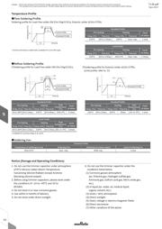
1. Soldering
(1) Can be soldered by reflow soldering method, flow
soldering method, and soldering iron.
(2) Soldering conditions
Refer to the temperature profile.
If the soldering conditions are not suitable, e.g.,
excessive time and/or excessive temperature, the
trimmer capacitor may deviate from the specified
characteristics.
(3) The amount of solder is critical.
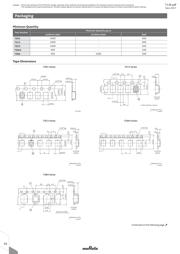
(4) The thickness of solder paste should be printed
from 150 micro m to 200 micro m and the dimension
of land pattern should be Murata's standard land
pattern used at reflow soldering. Insufficient
amounts of solder can lead to insufficient
soldering strength on PCB. Excessive amounts of
solder may cause bridging between the terminals
or contact failure due to flux wicking up.
(5) When using soldering iron, the string solder
shall be applied to the lower part of the
terminal only. Do not apply flux except to the
terminals. Excessive amounts of solder and/or
applying solder to the upper part of the
terminal may cause fixed rotor or contact failure
due to flux invasion into the movable part and/or
the contact point. The soldering iron should not
come in contact with the plastic case of the
trimmer capacitor. If such contact does occur,
the trimmer capacitor may be damaged.
(6) Our recommended chlorine content of solder is
as follows.
(a) Solder paste: 0.2wt% max.
(b) String solder: 0.5wt% max.
(7) Do not use water-soluble flux (for water
cleaning). To prevent the deterioration of
trimmer capacitor characteristics, apply flux
only to terminals.
2. Mounting
(1) Do not apply excessive force (preferably 5.0N
[Ref: 500gf] max.), when the trimmer capacitor
is mounted on the PCB.
(2) Do not warp and/or bend PCB to protect trimmer
capacitor from breakage.
(3) When bending the terminals, do not apply
excessive force to the body of the product to
protect the terminal fixing part from damage.
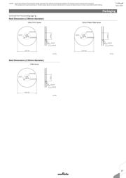
(4) Use a pick-up nozzle of a suitable dimension.
> Without cover film type
- External dimensions of 4.5x4.0mm and
2.5mm bore diameter.
> With cover film type
- 4.0mm external diameter and 2.0mm bore
diameter.
3. Cleaning [with cover film type]
Isopropyl alcohol and ethyl alcohol are available
material for cleaning. If you use any other type of
solvent, please evaluate performance in your
application. Moreover, please confirm that no
damage has occurred to the trimmer capacitor
after cleaning in your conditions.
4. Other
Note the polarity of the trimmer capacitor to
minimize influence by stray capacitance.
(Refer to the dimensions concerning the polarity.)
器件 Datasheet 文档搜索
AiEMA 数据库涵盖高达 72,405,303 个元件的数据手册,每天更新 5,000 多个 PDF 文件
