Datasheet 搜索 > 稳压芯片 > TI(德州仪器) > UC3825AQ 数据手册 > UC3825AQ 数据手册 7/19 页
 器件3D模型
¥ 33.225
UC3825AQ 数据手册 - TI(德州仪器)
制造商:
TI(德州仪器)
分类:
稳压芯片
封装:
PLCC-20
描述:
高速PWM控制器 High Speed PWM Controller
Pictures:
3D模型
符号图
焊盘图
引脚图
产品图
页面导航:
引脚图在P2Hot
原理图在P1P11
封装尺寸在P12P13P14P15P17P18
型号编码规则在P2
标记信息在P12P13P14P15
封装信息在P12P13P14P15P16P17P18
技术参数、封装参数在P3
应用领域在P16P19
电气规格在P4P5

导航目录
UC3825AQ数据手册
Page:
of 19 Go
若手册格式错乱,请下载阅览PDF原文件
UC1823A, UC2823A, UC2823B,
UC3823A, UC3823B, UC1825A,
UC2825A, UC2825B, UC3825A, UC3825B
SLUS334E − AUGUST 1995 − REVISED SEPTEMBER 2010
www.ti.com
7
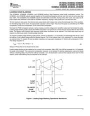
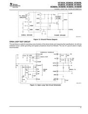
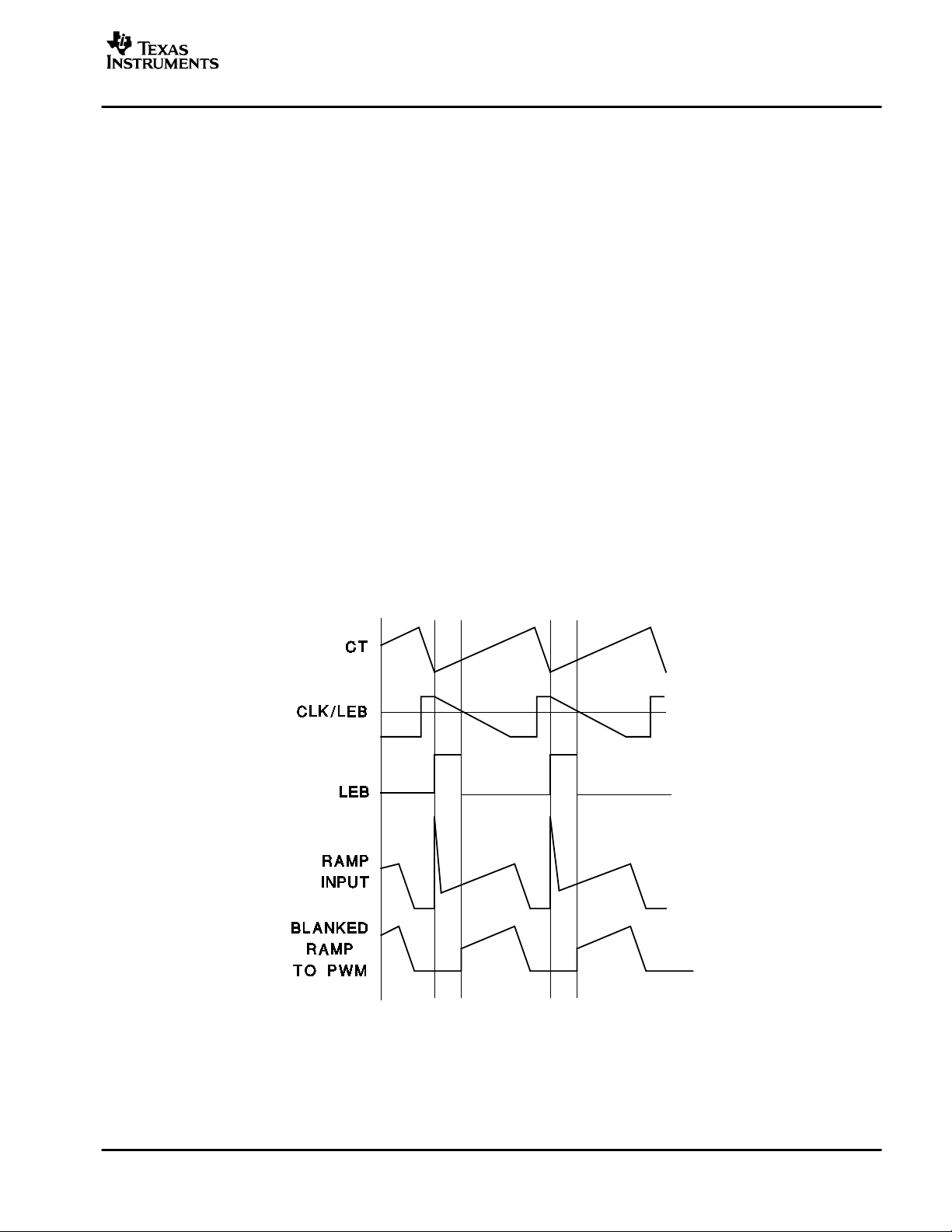
LEADING EDGE BLANKING
The UC3823A, UC2823B, UC3825A, and UC3825B perform fixed frequency pulse width modulation control. The
UC3823A, and UC3823B outputs operate together at the switching frequency and can vary from zero to some value less
than 100%. The UC3825A and UC3825B outputs are alternately controlled. During every other cycle, one output is off.
Each output then switches at one-half the oscillator frequency, varying in duty cycle from 0 to less than 50%.
To limit maximum duty cycle, the internal clock pulse blanks both outputs low during the discharge time of the oscillator.
On the falling edge of the clock, the appropriate output(s) is driven high. The end of the pulse is controlled by the PWM
comparator, current limit comparator, or the overcurrent comparator.
Normally the PWM comparator senses a ramp crossing a control voltage (error amplifier output) and terminates the pulse.
Leading edge blanking (LEB) causes the PWM comparator to be ignored for a fixed amount of time after the start of the
pulse. This allows noise inherent with switched mode power conversion to be rejected. The PWM ramp input may not
require any filtering as result of leading edge blanking.
To program a leading edge blanking (LEB) period, connect a capacitor, C, to CLK/LEB. The discharge time set by C and
the internal 10-kΩ resistor determines the blanked interval. The 10-kΩ resistor has a 10% tolerance. For more accuracy,
an external 2-kΩ 1% resistor (R) can be added, resulting in an equivalent resistance of 1.66 kΩ with a tolerance of 2.4%.
The design equation is:
t
LEB
+ 0.5
ǒ
R ø 10 kW
Ǔ
C
Values of R less than 2 kΩ should not be used.
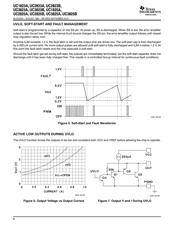
Leading edge blanking is also applied to the current limit comparator. After LEB, if the ILIM pin exceeds the 1-V threshold,
the pulse is terminated. The overcurrent comparator, however, is not blanked. It catches catastrophic overcurrent faults
without a blanking delay. Any time the ILIM pin exceeds 1.2 V, the fault latch is set and the outputs driven low. For this
reason, some noise filtering may be required on the ILIM pin.
UDG−95105
Figure 4. Leading Edge Blanking Operational Waveforms
(2)
器件 Datasheet 文档搜索
AiEMA 数据库涵盖高达 72,405,303 个元件的数据手册,每天更新 5,000 多个 PDF 文件
