Datasheet 搜索 > TI(德州仪器) > UCC28950PWTR 数据手册 > UCC28950PWTR 数据手册 1/20 页

¥ 0
UCC28950PWTR 数据手册 - TI(德州仪器)
制造商:
TI(德州仪器)
描述:
绿色环保相移全桥控制器采用同步整流 Green Phase-Shifted Full-Bridge Controller With Synchronous Rectification
Pictures:
3D模型
符号图
焊盘图
引脚图
产品图
页面导航:
导航目录
UCC28950PWTR数据手册
Page:
of 20 Go
若手册格式错乱,请下载阅览PDF原文件
www.ti.com
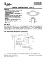
FEATURES
1
2
3
4
8
7
6
5
VIN
SD/FB
RESB
CT
VGD
VOUT
SW
GND
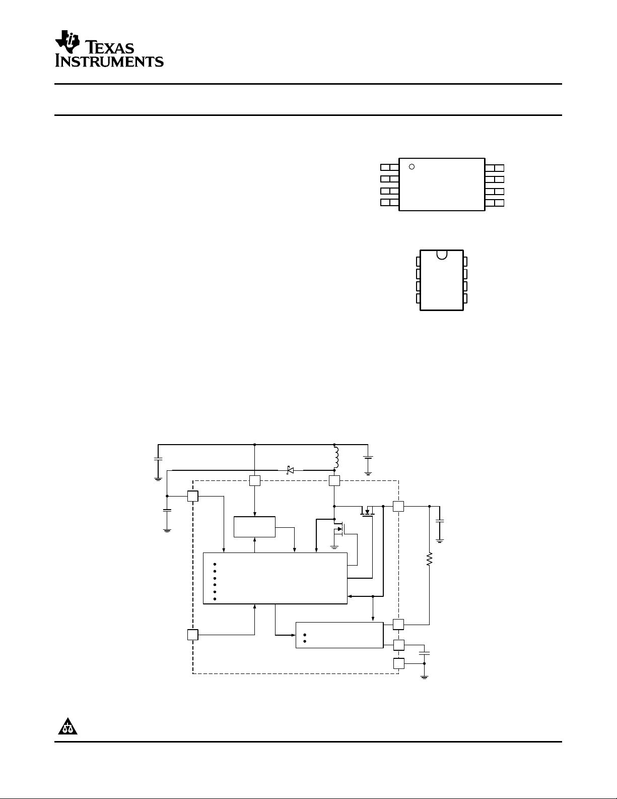
PW PACKAGE
(TOP VIEW)
1
2
3
4
8
7
6
5
VOUT
VGD
VIN
SD/FB
SW
GND
CT
RESB
D PACKAGE
(TOP VIEW)
DESCRIPTION
SIMPLIFIED BLOCK DIAGRAM AND APPLICATION CIRCUIT
1
4
7
6
VOUT
GND
3.3 V 200 mW
5
R
RES
3
100
µ
F
RESET CONTROL CIRCUIT
GLITCH SUPRESSION
PROGRAMMABLE TIMING
MODULATOR CONTROL CIRCUIT
SYNCHRONOUS RECTIFICATION CIRCUITRY
ANTI–CROSS CONDUCTION
START–UP
MULTIPLEXING LOGIC
MAX INPUT POWER CONTROL
ADAPTIVE CURRENT CONTROL
START–UP
CIRCUITRY
1.2
Ω
CT
RESB
2SD/FB
100
µ
F
VIN
SW
8
VGD
0.5
Ω
100
µ
F
1 V TO 3.5 V
22
µ
H
+
C
T
UCC29411, UCC29412
UCC29413, UCC39411
UCC39412, UCC39413
SLUS245E – MARCH 2000 – REVISED JULY 2005
LOW-POWER SYNCHRONOUS BOOST CONVERTER
• 1 V Input Voltage Operation Start-Up Ensured
Under Full Load on Main Output, and
Operation Down to 0.5 V
• 200 mW Output Power at Battery Voltages as
Low as 0.8 V
• Secondary 7 V Supply from a Single Inductor
• Output Fully Disconnected in Shutdown
• Adaptive Current Mode Control for Optimum
Efficiency
• High Efficiency Over Wide Operating Range
• 6 µA Shutdown Supply Current
• Output Reset Function with Programmable
Reset Period
The UCCx9411 family of low-input voltage, single-inductor-boost converters is optimized to operate from a single
or dual alkaline cell, and steps up to a 3.3 V, 5 V, or adjustable output at 200 mW. The UCCx9411 family also
provides an auxiliary 7 V output, primarily for the gate-drive supply, which can be used for applications requiring
an auxiliary output, such as 5 V, by linear regulating. The primary output starts up under full load at input
voltages typically as low as 0.8 V with a ensured max of 1 V, and operates down to 0.5 V once the converter is
operating, thereby maximizing battery usage.
A. Pinout shown is for the TSSOP Package. Consult Package Descriptions for the SOIC configurations.
Please be aware that an important notice concerning availability, standard warranty, and use in critical applications of Texas
Instruments semiconductor products and disclaimers thereto appears at the end of this data sheet.
PRODUCTION DATA information is current as of publication date.
Copyright © 2000–2005, Texas Instruments Incorporated
Products conform to specifications per the terms of the Texas
Instruments standard warranty. Production processing does not
necessarily include testing of all parameters.
器件 Datasheet 文档搜索
AiEMA 数据库涵盖高达 72,405,303 个元件的数据手册,每天更新 5,000 多个 PDF 文件
