Datasheet 搜索 > 接口芯片 > TI(德州仪器) > ULN2003BDR 数据手册 > ULN2003BDR 数据手册 5/23 页
 器件3D模型
¥ 0.555
ULN2003BDR 数据手册 - TI(德州仪器)
制造商:
TI(德州仪器)
分类:
接口芯片
封装:
SOIC-16
描述:
ULN2003BDR 编带
Pictures:
3D模型
符号图
焊盘图
引脚图
产品图
页面导航:
引脚图在P3Hot
典型应用电路图在P10P11
原理图在P1P9
封装尺寸在P14P16P17
标记信息在P14
封装信息在P13P14P15P16P17
技术参数、封装参数在P4
应用领域在P1P9P23
电气规格在P5

导航目录
ULN2003BDR数据手册
Page:
of 23 Go
若手册格式错乱,请下载阅览PDF原文件
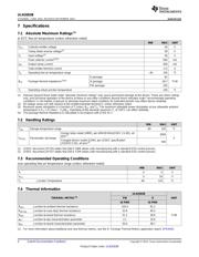
ULN2003B
www.ti.com
SLRS064A –JUNE 2014–REVISED SEPTEMBER 2014
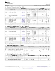
7.5 Electrical Characteristics, T
A
= 25°C
TEST FIGURE ULN2003B
PARAMETER TEST CONDITIONS UNIT
MIN TYP MAX
I
C
= 200 mA 2.4
V
I(on)
On-state input voltage Figure 12 V
CE
= 2 V I
C
= 250 mA 2.7 V
I
C
= 300 mA 3
I
I
= 250 μA, I
C
= 100 mA 0.9 1.1
Collector-emitter saturation
V
CE(sat)
Figure 11 I
I
= 350 μA, I
C
= 200 mA 1 1.3 V
voltage
I
I
= 500 μA, I
C
= 350 mA 1.2 1.6
I
CEX
Collector cutoff current Figure 8 V
CE
= 50 V, I
I
= 0 10 μA
V
F
Clamp forward voltage Figure 14 I
F
= 350 mA 1.7 2 V
I
I(off)
Off-state input current Figure 9 V
CE
= 50 V, I
C
= 500 μA 50 65 μA
I
I
Input current Figure 10 V
I
= 3.85 V 0.93 1.35 mA
I
R
Clamp reverse current Figure 13 V
R
= 50 V 50 μA
C
i
Input capacitance V
I
= 0, f = 1 MHz 15 25 pF
7.6 Electrical Characteristics, T
A
= –40°C to 105°C
PARAMETER TEST FIGURE TEST CONDITIONS ULN2003B UNIT
MIN TYP MAX
I
C
= 200 mA 2.7
V
I(on)
On-state input voltage Figure 12 V
CE
= 2 V I
C
= 250 mA 2.9 V
I
C
= 300 mA 3
I
I
= 250 μA, I
C
= 100 mA 0.9 1.2
V
CE(sat)
Collector-emitter saturation voltage Figure 11 I
I
= 350 μA, I
C
= 200 mA 1 1.4 V
I
I
= 500 μA, I
C
= 350 mA 1.2 1.7
I
CEX
Collector cutoff current Figure 8 V
CE
= 50 V, I
I
= 0 20 μA
V
F
Clamp forward voltage Figure 14 I
F
= 350 mA 1.7 2.2 V
I
I(off)
Off-state input current Figure 9 V
CE
= 50 V, I
C
= 500 μA 30 65 μA
I
I
Input current Figure 10 V
I
= 3.85 V 0.93 1.35 mA
I
R
Clamp reverse current Figure 13 V
R
= 50 V 100 μA
C
i
Input capacitance V
I
= 0, f = 1 MHz 15 25 pF
7.7 Switching Characteristics, T
A
= 25°C
PARAMETER TEST CONDITIONS MIN TYP MAX UNIT
t
PLH
Propagation delay time, low- to high-level output 0.25 1 μs
t
PHL
Propagation delay time, high- to low-level output 0.25 1 μs
V
S
–
V
OH
High-level output voltage after switching V
S
= 50 V, I
O
≈ 300 mA mV
20
7.8 Switching Characteristics, T
A
= –40°C to 105°C
PARAMETER TEST CONDITIONS MIN TYP MAX UNIT
t
PLH
Propagation delay time, low- to high-level output 1 10 μs
t
PHL
Propagation delay time, high- to low-level output 1 10 μs
V
S
–
V
OH
High-level output voltage after switching V
S
= 50 V, I
O
≈ 300 mA mV
50
Copyright © 2014, Texas Instruments Incorporated Submit Documentation Feedback 5
Product Folder Links: ULN2003B
器件 Datasheet 文档搜索
AiEMA 数据库涵盖高达 72,405,303 个元件的数据手册,每天更新 5,000 多个 PDF 文件
