Datasheet 搜索 > 接口芯片 > Microchip(微芯) > USB3343-CP 数据手册 > USB3343-CP 数据手册 6/92 页
 器件3D模型
¥ 10.416
USB3343-CP 数据手册 - Microchip(微芯)
制造商:
Microchip(微芯)
分类:
接口芯片
封装:
QFN-24
描述:
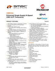
USB334x 系列 USB 2.0 收发器Microchip 的 USB334x 系列设备是高速 USB2.0 ULPI 收发器,支持 USB-IF 电池充电 1.2 (BC 1.2) 规格。### 特点符合 USB-IF 电池充电 1.2 规格 符合链路电源管理 (LPM) 规格 集成 ESD 保护电路 - 高达 ±25KV IEC 空气放电,无需外部设备 过压保护电路 (OVP) - 防止 VBUS 引脚受到电压高达 30V 的连续直流的损坏 集成 USB 开关 - 仅限 USB3341、USB3346 和 USB3347 型号 Microchip 的 RapidCharge Anywhere™: \- 通过 USB 端口的充电电流是传统解决方案的 3 倍 \- 符合 USB-IF 电池充电 1.2 规格,适用于任何便携式设备 \- 通过兼容 USB 主机或专用充电器的充电电流高达 1.5A \- 专用充电端口 (DCP)、充电 (CDP) 和标准 (SDP) 下游端口支持 flexPWR® 技术 - 极低电流设计,特别适用于电池供电应用 单电源操作 - 集成 1.8V 和 3.3V 调节器 PHYBoost - 可编程 USB 收发器驱动强度,用于还原信号完整性 VariSense™ - 可编程 USB 接收器灵敏度 免包装设计,用于优化定时性能和简化设计 提供外部参考时钟操作 智能检测电路允许识别 USB 充电器、耳机或数据电缆插入 包括对 On-The-Go 补充修订版 2.0 规格中详述的可选 On-The-Go (OTG) 协议的全面支持 支持 OTG 主机协商协议 (HNP) 和会话请求协议 (SRP) UART 模式,用于非 USB 串行数据传输 ID、DP 和 DM 线路至 VBUS 或接地连接内部 5V 电缆短路保护 ### USB (通用串行总线)- Microchip展开
Pictures:
3D模型
符号图
焊盘图
引脚图
产品图
页面导航:
引脚图在P11P12P13P14P15P16P65P66P67P69Hot
典型应用电路图在P2P42
原理图在P9P10P45P48
封装尺寸在P88
标记信息在P91
封装信息在P89P90
功能描述在P8
技术参数、封装参数在P17P20P27
应用领域在P1
电气规格在P19P24P25

导航目录
USB3343-CP数据手册
Page:
of 92 Go
若手册格式错乱,请下载阅览PDF原文件

Enhanced Single Supply Hi-Speed USB ULPI Transceiver
Datasheet
Revision 1.2 (02-08-13) 6 SMSC USB334x
DATASHEET
List of Figures
Figure 1.1 Block Diagram (USB3341, USB3346, and USB3347) . . . . . . . . . . . . . . . . . . . . . . . . . . . . . . . 9
Figure 1.2 Block Diagram (USB3343) . . . . . . . . . . . . . . . . . . . . . . . . . . . . . . . . . . . . . . . . . . . . . . . . . . . 10
Figure 2.1 USB3341, USB3346, and USB3347 Pin Locations - Top View . . . . . . . . . . . . . . . . . . . . . . . 11
Figure 2.2 USB3343 Pin Locations - Top View . . . . . . . . . . . . . . . . . . . . . . . . . . . . . . . . . . . . . . . . . . . . 14
Figure 5.1 USB334x System Diagram (USB3341, USB3346, and USB3347) . . . . . . . . . . . . . . . . . . . . 29
Figure 5.2 USB334x System Diagram (USB3343) . . . . . . . . . . . . . . . . . . . . . . . . . . . . . . . . . . . . . . . . . 30
Figure 5.1 Configuring the USB334x for ULPI Clock Input Mode (60 MHz) . . . . . . . . . . . . . . . . . . . . . . 34
Figure 5.2 Configuring the USB334x for ULPI Clock Output Mode. . . . . . . . . . . . . . . . . . . . . . . . . . . . . 35
Figure 5.3 Example of Circuit Used to Shift a Reference Clock Common-mode Voltage Level . . . . . . . 35
Figure 5.4 ULPI Start-up Timing . . . . . . . . . . . . . . . . . . . . . . . . . . . . . . . . . . . . . . . . . . . . . . . . . . . . . . . 38
Figure 5.5 USB334x ID Resistor Detection Circuitry. . . . . . . . . . . . . . . . . . . . . . . . . . . . . . . . . . . . . . . . 39
Figure 5.6 USB334x OTG VBUS Block. . . . . . . . . . . . . . . . . . . . . . . . . . . . . . . . . . . . . . . . . . . . . . . . . . 41
Figure 5.7 USB Charger Detection Block Diagram . . . . . . . . . . . . . . . . . . . . . . . . . . . . . . . . . . . . . . . . . 45
Figure 6.1 ULPI Digital Block Diagram . . . . . . . . . . . . . . . . . . . . . . . . . . . . . . . . . . . . . . . . . . . . . . . . . . 48
Figure 6.2 ULPI Single Data Rate Timing Diagram in Synchronous Mode. . . . . . . . . . . . . . . . . . . . . . . 50
Figure 6.3 ULPI Register Write in Synchronous Mode . . . . . . . . . . . . . . . . . . . . . . . . . . . . . . . . . . . . . . 52
Figure 6.4 ULPI Extended Register Write in Synchronous Mode . . . . . . . . . . . . . . . . . . . . . . . . . . . . . . 53
Figure 6.5 ULPI Register Read in Synchronous Mode . . . . . . . . . . . . . . . . . . . . . . . . . . . . . . . . . . . . . . 53
Figure 6.6 ULPI Extended Register Read in Synchronous Mode . . . . . . . . . . . . . . . . . . . . . . . . . . . . . . 54
Figure 6.7 ULPI RXCMD Timing . . . . . . . . . . . . . . . . . . . . . . . . . . . . . . . . . . . . . . . . . . . . . . . . . . . . . . . 55
Figure 6.8 ULPI Receive in Synchronous Mode . . . . . . . . . . . . . . . . . . . . . . . . . . . . . . . . . . . . . . . . . . . 58
Figure 6.9 ULPI Transmit in Synchronous Mode . . . . . . . . . . . . . . . . . . . . . . . . . . . . . . . . . . . . . . . . . . 60
Figure 6.10 LPM Token Transmit . . . . . . . . . . . . . . . . . . . . . . . . . . . . . . . . . . . . . . . . . . . . . . . . . . . . . . . 61
Figure 6.11 Entering Low Power Mode from Synchronous Mode. . . . . . . . . . . . . . . . . . . . . . . . . . . . . . . 62
Figure 6.12 Exiting Low Power Mode . . . . . . . . . . . . . . . . . . . . . . . . . . . . . . . . . . . . . . . . . . . . . . . . . . . . 63
Figure 8.1 USB3341, USB3346, and USB3347 Application Diagram (Device configured for ULPI Clock
Output Mode) 84
Figure 8.2 USB3343 Application Diagram (Device configured for ULPI Clock Output Mode) . . . . . . . . 85
Figure 8.3 USB3341, USB3346, and USB3347 Application Diagram (Host or OTG configured for ULPI
Clock Input mode) 86
Figure 9.1 24-pin QFN, 4x4mm Body, 0.5mm Pitch . . . . . . . . . . . . . . . . . . . . . . . . . . . . . . . . . . . . . . . . 88
Figure 9.2 24QFN, 4x4 Tape and Reel . . . . . . . . . . . . . . . . . . . . . . . . . . . . . . . . . . . . . . . . . . . . . . . . . . 89
Figure 9.3 24QFN, 4x4 Reel Dimensions . . . . . . . . . . . . . . . . . . . . . . . . . . . . . . . . . . . . . . . . . . . . . . . . 90
Figure 9.4 24QFN, 4x4 Package Marking . . . . . . . . . . . . . . . . . . . . . . . . . . . . . . . . . . . . . . . . . . . . . . . . 91
器件 Datasheet 文档搜索
AiEMA 数据库涵盖高达 72,405,303 个元件的数据手册,每天更新 5,000 多个 PDF 文件
