Datasheet 搜索 > 接口芯片 > Microchip(微芯) > USB3343-CP 数据手册 > USB3343-CP 数据手册 63/92 页
 器件3D模型
¥ 10.413
USB3343-CP 数据手册 - Microchip(微芯)
制造商:
Microchip(微芯)
分类:
接口芯片
封装:
QFN-24
描述:
USB334x 系列 USB 2.0 收发器Microchip 的 USB334x 系列设备是高速 USB2.0 ULPI 收发器,支持 USB-IF 电池充电 1.2 (BC 1.2) 规格。### 特点符合 USB-IF 电池充电 1.2 规格 符合链路电源管理 (LPM) 规格 集成 ESD 保护电路 - 高达 ±25KV IEC 空气放电,无需外部设备 过压保护电路 (OVP) - 防止 VBUS 引脚受到电压高达 30V 的连续直流的损坏 集成 USB 开关 - 仅限 USB3341、USB3346 和 USB3347 型号 Microchip 的 RapidCharge Anywhere™: \- 通过 USB 端口的充电电流是传统解决方案的 3 倍 \- 符合 USB-IF 电池充电 1.2 规格,适用于任何便携式设备 \- 通过兼容 USB 主机或专用充电器的充电电流高达 1.5A \- 专用充电端口 (DCP)、充电 (CDP) 和标准 (SDP) 下游端口支持 flexPWR® 技术 - 极低电流设计,特别适用于电池供电应用 单电源操作 - 集成 1.8V 和 3.3V 调节器 PHYBoost - 可编程 USB 收发器驱动强度,用于还原信号完整性 VariSense™ - 可编程 USB 接收器灵敏度 免包装设计,用于优化定时性能和简化设计 提供外部参考时钟操作 智能检测电路允许识别 USB 充电器、耳机或数据电缆插入 包括对 On-The-Go 补充修订版 2.0 规格中详述的可选 On-The-Go (OTG) 协议的全面支持 支持 OTG 主机协商协议 (HNP) 和会话请求协议 (SRP) UART 模式,用于非 USB 串行数据传输 ID、DP 和 DM 线路至 VBUS 或接地连接内部 5V 电缆短路保护 ### USB (通用串行总线)- Microchip展开
Pictures:
3D模型
符号图
焊盘图
引脚图
产品图
页面导航:
引脚图在P11P12P13P14P15P16P65P66P67P69Hot
典型应用电路图在P2P42
原理图在P9P10P45P48
封装尺寸在P88
标记信息在P91
封装信息在P89P90
功能描述在P8
技术参数、封装参数在P17P20P27
应用领域在P1
电气规格在P19P24P25
导航目录
USB3343-CP数据手册
Page:
of 92 Go
若手册格式错乱,请下载阅览PDF原文件
Enhanced Single Supply Hi-Speed USB ULPI Transceiver
Datasheet
SMSC USB334x 63 Revision 1.2 (02-08-13)
DATASHEET
Note 6.1 LineState: These signals reflect the current state of the Full-Speed single ended receivers.
LineState[0] directly reflects the current state of DP. LineState[1] directly reflects the current
state of DM. When DP=DM=0 this is called "Single Ended Zero" (SE0). When DP=DM=1,
this is called "Single Ended One" (SE1).
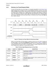
An unmasked interrupt can be caused by the following comparators changing state: VbusVld, SessVld,
SessEnd, and IdGnd. If any of these signals change state during Low Power Mode and the bits are
enabled in either the USB Interrupt Enable Rising or USB Interrupt Enable Falling registers, DATA[3]
will assert. During Low Power Mode, the VbusVld and SessEnd comparators can have their interrupts
masked to lower the suspend current as described in Section 6.5.5.
While in Low Power Mode, the Data bus is driven asynchronously because all of the PHY clocks are
stopped during Low Power Mode.
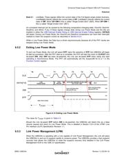
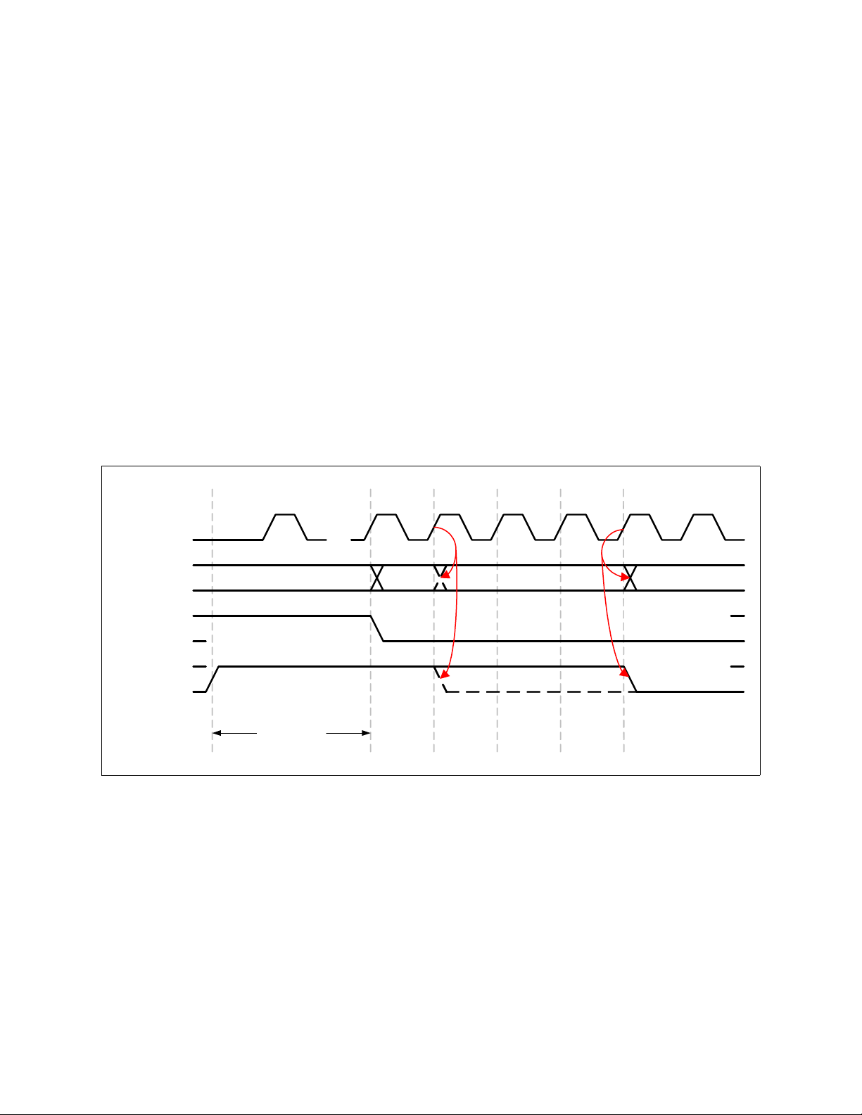
6.5.2 Exiting Low Power Mode
To exit Low Power Mode, the Link will assert STP. Upon the assertion of STP, the USB334x will begin
its start-up procedure. After the PHY start-up is complete, the PHY will start the clock on CLKOUT and
de-assert DIR. After DIR has been de-asserted, the Link can de-assert STP when ready and start
operating in Synchronous Mode. The PHY will automatically set the SuspendM bit to a 1 in the
Function Control register.
The value for T
START
is given in Ta b le 4 .3 .
Should the Link de-assert STP before DIR is de-asserted, the USB334x will detect this as a false
resume request and return to Low Power Mode. This is detailed in Section 3.9.4 of the UTMI+ Low
Pin Interface (ULPI) Specification Revision 1.1.
6.5.3 Link Power Management (LPM)
When the USB334x is operating with a Link capable of Link Power Management, the Link will place
the USB334x in and out of suspend rapidly to conserve power. The USB334x provides a fast suspend
recovery that allows the USB334x to meet the suspend recovery time detailed in the Link Power
Management ECN to the USB 2.0 specification.
Figure 6.12 Exiting Low Power Mode
DIR
CLK
DATA[7:0]
STP
TURN
AROUND
LOW
POWER MODE
DATA BUS IGNORED (SLOW LINK)
IDLE (FAST LINK)
IDLE
T0 T1 T2 T3 T5T4
Slow Link Drives Bus
Idle and STP low
Fast Link Drives Bus
Idle and STP low
...
Note: Not to Scale
T
START
器件 Datasheet 文档搜索
AiEMA 数据库涵盖高达 72,405,303 个元件的数据手册,每天更新 5,000 多个 PDF 文件
