Datasheet 搜索 > Brumfield > V23026A1002B201 数据手册 > V23026A1002B201 数据手册 1/5 页

¥ 27.93
V23026A1002B201 数据手册 - Brumfield
制造商:
Brumfield
Pictures:
3D模型
符号图
焊盘图
引脚图
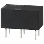
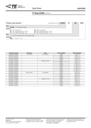
产品图
页面导航:
典型应用电路图在P1
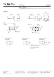
封装信息在P2P4
焊接温度在P4
技术参数、封装参数在P1
导航目录
V23026A1002B201数据手册
Page:
of 5 Go
若手册格式错乱,请下载阅览PDF原文件
03-2016, Rev. 0316
www.te.com
© 2011 Tyco Electronics Corporation,
a TE Connectivity Ltd. company
Datasheets and product specification
according to IEC 61810-1 and to be used
only together with the ‘Definitions’ section.
Datasheets and product data is subject to the
terms of the disclaimer and all chapters of
the ‘Definitions’ section, available at
http://relays.te.com/definitions
Datasheets, product data, ‘Definitions’ sec-
tion, application notes and all specifications
are subject to change.
1
AXICOM
Signal Relays
P1 Relay V23026
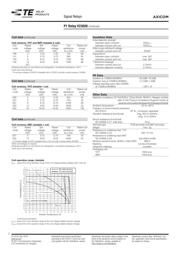
Coil Data
Magnetic system polarized
Coil voltage range 3 to 24VDC
other coil voltages on request
Operative range, IEC 61810 see coil operative range
Max. coil temperature 85°C
Thermal resistance <130K/W
Coil versions, THT, monostable
Coil Rated Operate Release Coil Rated coil
code voltage voltage voltage resistance power
VDC VDC
min.
VDC
min.
Ω ±10% mW
006 3 2.25 0.3 137 66
001 5 3.75 0.5 370 68
005 9 6.75 0.9 1165 70
002 12 9.00 1.2 2250 34
004 24 18.00 2.4 4500 128
All figures are given for coil without pre-energization, at ambient temperature +23°C.
Coil versions, SMT, monostable
Coil Rated Operate Release Coil Rated coil
code voltage voltage voltage resistance power
VDC VDC
min.
VDC
min.
Ω ±10% mW
026 3 2.25 0.3 113 80
021 5 3.75 0.5 313 80
025 9 6.75 0.9 1015 80
022 12 9.00 1.2 1800 80
024 24 18.00 2.4 4500 128
All figures are given for coil without pre-energization, at ambient temperature +23°C.
Coil operative range, monostable DC coil
n
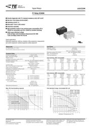
Directly triggerable with TTL standard modules as ALS, HCT & ACT
n
Slim line 13.5x7.85mm (0.531x0.309”)
n
Switching current 1 A
n
Bifurcated 1 form C (CO) contact
n
Immersion cleanable
n
High sensitivity results in low nominal power consumption, 65 to
130mW for monostable and 30 to 150mW for bistable (latching)
n
Initial surge withstand voltage
2.5kV (2/10μs) meets the Bellcore Requirement GR-1089
1.5kV (10/160μs) meets FCC Part 68
Typical applications
Automotive equipment, CAN bus, imobilizer, office equipment, measurement
and control equipment, medical equipment, safety equipment
Approvals
UL 508 File No. E 111441
Technical data of approved types on request
Contact Data
Contact arrangement 1 form C (CO)
Max. switching voltage 125VDC, 150VAC
Rated current 1A
Limiting continuous current, 85°C 1A
Breaking capacity max. see max. DC load breaking capacity
Contact material Palladium nickel,
gold-rhodium covered
Contact style bifurcated contact
Min. recommended contact load 10mA at 20mV
Initial contact resistance ≤50mΩ at 10mA/20mV
Frequency of operation without load 200 ops./s
Operate/release time max. 2ms
Set/reset time max. 2ms
Bounce time max. 3ms
Electrical endurance
at 12V/10mA typ. 50x10
6
operations
at 6V/100mA typ. 10x10
6
operations
at 30V/1000mA typ. 10x10
3
operations
Contact ratings
UL contact ratings 30VDC/1A
65VDC/0.46A
150VAC/0.46A
Mechanical endurance typ. 10
9
operations
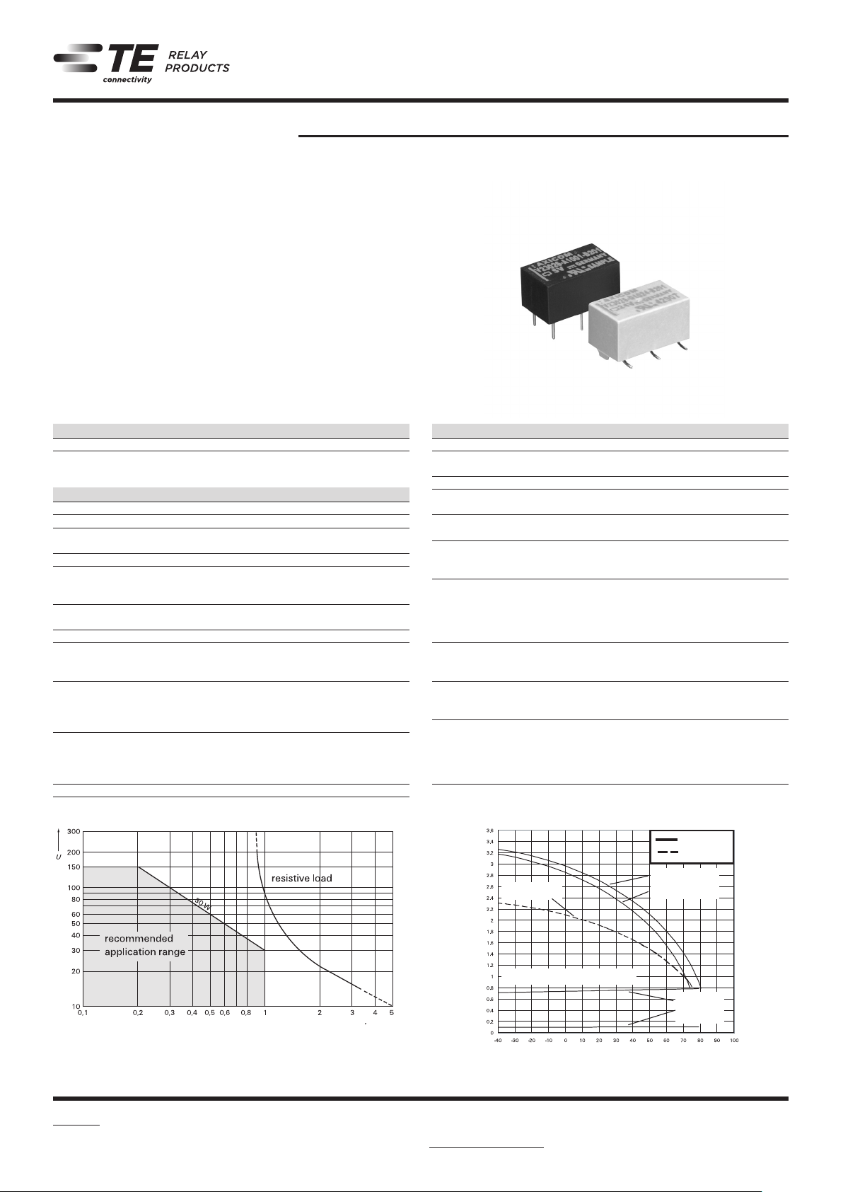
Max. DC load breaking capacity
108-98009 Rev. E
All specifications subject to change. Consult Tyco Electronics for latest specifications.
7 of 12
Telecom-, Signal and RF Relays
P1 V23026 Relay
AXICOM
Contact Data
Number of contacts and type 1 changeover contact
Contact assembly Bifurcated contact
Contact material Palladium nickel, gold-rhodium covered
Limiting continuous current at max. ambient temperature 1 A
Maximum switching current 1 A
Maximum swichting voltage 125 Vdc
150 Vac
Maximum switching capacity 30 W, 60 VA
Thermoelectric potential < 100 µV
Initial contact resistance / measuring condition: 10 mA / 20 mV < 50 m
Electrical endurance at 12 V / 10 mA
at 6 V / 100 mA
at 30 V / 1000 mA
typ. 5 x 10
7
operations
typ. 1 x 10
7
operations
typ. 1 x 10
4
operations
Mechanical endurance typ. 10
9
operations
UL contact ratings 30 Vdc / 1 A
65 Vdc / 0.46 A
150 Vac / 0.46 A
Max. DC Load Breaking Capacity
108-98009 Rev. E
All specifications subject to change. Consult Tyco Electronics for latest specifications.
5 of 12
Telecom-, Signal and RF Relays
P1 V23026 Relay
AXICOM
Coil Operating Range
U
nom
= Nominal coil voltage
U
max.
= Upper limit of the operative range of
the coil voltage (limiting voltage)
when coils are continously energized
U
op. min.
= Lower limit of the operative range of
the coil voltage (reliable operate
voltage)
U
rel. min.
= Lower limit of the operative range of
the coil voltage (reliable release
voltage)
Umax. at 0 A
U
max. at - 1 A
Unom. nominal coil voltage
Uop. min.
Urel. min.
Ambient Temperature [°C]
Coil Voltage [U/U
nom
]
Umax. at 0 A
65 mW
130 mW
Ambient Temperature [°C]
Coil Voltage [U/U
nom]
Unom. nominal coil voltage
Umax. - 100 % coil duty at 0 A
65 mW Latching
32 mW Latching
U
max. - 5 % coil duty at 1 A
Umax. - 5 % coil duty at 0 A
Uset min.
Z
P1_THTSMD
器件 Datasheet 文档搜索
AiEMA 数据库涵盖高达 72,405,303 个元件的数据手册,每天更新 5,000 多个 PDF 文件
