Datasheet 搜索 > Brumfield > V23100V4305C010 数据手册 > V23100V4305C010 数据手册 1/4 页


¥ 64.516
V23100V4305C010 数据手册 - Brumfield
制造商:
Brumfield
Pictures:
3D模型
符号图
焊盘图
引脚图
产品图
页面导航:
典型应用电路图在P1
型号编码规则在P1P2P3
技术参数、封装参数在P1


导航目录
V23100V4305C010数据手册
Page:
of 4 Go
若手册格式错乱,请下载阅览PDF原文件
07-2015, Rev. 0715
www.te.com
© 2015 Tyco Electronics Corporation,
a TE Connectivity Ltd. company
Datasheets and product specification
according to IEC 61810-1 and to be used
only together with the ‘Definitions’ section.
Datasheets and product data is subject to the
terms of the disclaimer and all chapters of
the ‘Definitions’ section, available at
http://relays.te.com/definitions
Datasheets, product data, ‘Definitions’ sec-
tion, application notes and all specifications
are subject to change.
1
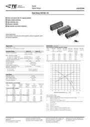
AXICOM
Signal
Signal Relays
n
Direct coil control with TTL-signals possible
n
Highly reliable switching
n
High switching rates
n
Ultrasonic cleanable
n
High vibration and shock resistance
Typical applications
Incircuit tester, measuring and control systems, telecom equipment, alarm
and security equipment.
Approvals
UL File No. 111441
Technical data of approved types on request.
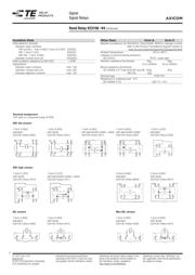
Contact Data form A form C
Contact arrangement 1 form A (1 NO), 1 form C (CO)
2 form A (2 NO)
Max. switching voltage
at rated coil voltage 5VDC 200VDC/VAC
peak
175VDC
at rated coil voltage 12to 24VDC 200VDC/VAC
peak
175VDC
peak
Limiting continuous current 1A 1.2A
Switching power 10W, 10VA 3W, 3VA
Contact material Ruthenium
Contact style reed contact
Initial contact resistance <150mΩ
Operate / release time max. 0.75/0.15ms 1.1/1.6ms
Electrical endurance
at 12V/10mA 50x10
6
operations
at 24V/400mA 5x10
6
operations
Coil Data
Magnetic system neutral
Coil voltage range 5 to 24VDC
Max. coil temperature 105°C
Thermal resistance < 75K/W
Coil versions, monostable
Coil Rated Operate Release Coil Rated coil
code voltage voltage voltage resistance power
VDC VDC
min.
VDC
min.
Ω±10% mW
1 form A (1 NO) contact
05 5VDC 3.5 0.75 500 50
12 12VDC 8.4 1.80 1000 144
15 15VDC 10.5 2.25 2000 112
24 24VDC 16.8 3.60 2000 288
2 form A (2 NO) or 1 form C (1 CO) contact
05 5VDC 3.5 0.75 200 125
12 12VDC 8.4 1.80 500 288
15 15VDC 10.5 2.25 2000 112
24 24VDC 16.8 3.60 2000 288
All figures are given for coil without pre-energization, at ambient temperature +23°C.
Coil Data (continued)
Coil versions, limiting operate voltage
Coil DIP flat, DIP flat DIP high DIP high DIP high Mini SIL
code SIL, 1 form A 1 form C 2 form A 1 form C 1 form A
1 form A with diode std,diode diode+
shield
VDC VDC VDC VDC VDC VDC
05 22.0 14.0 13.0 14.0 14.5 13.6
12 33.0 25.0 22.0 25.0 23.5 21.6
15 44.0 47.0 44.0 47.0 14.5 -
24 44.0 47.0 44.0 47.0 49.0 -
All figures are given for coil without pre-energization, at ambient temperature +23°C.
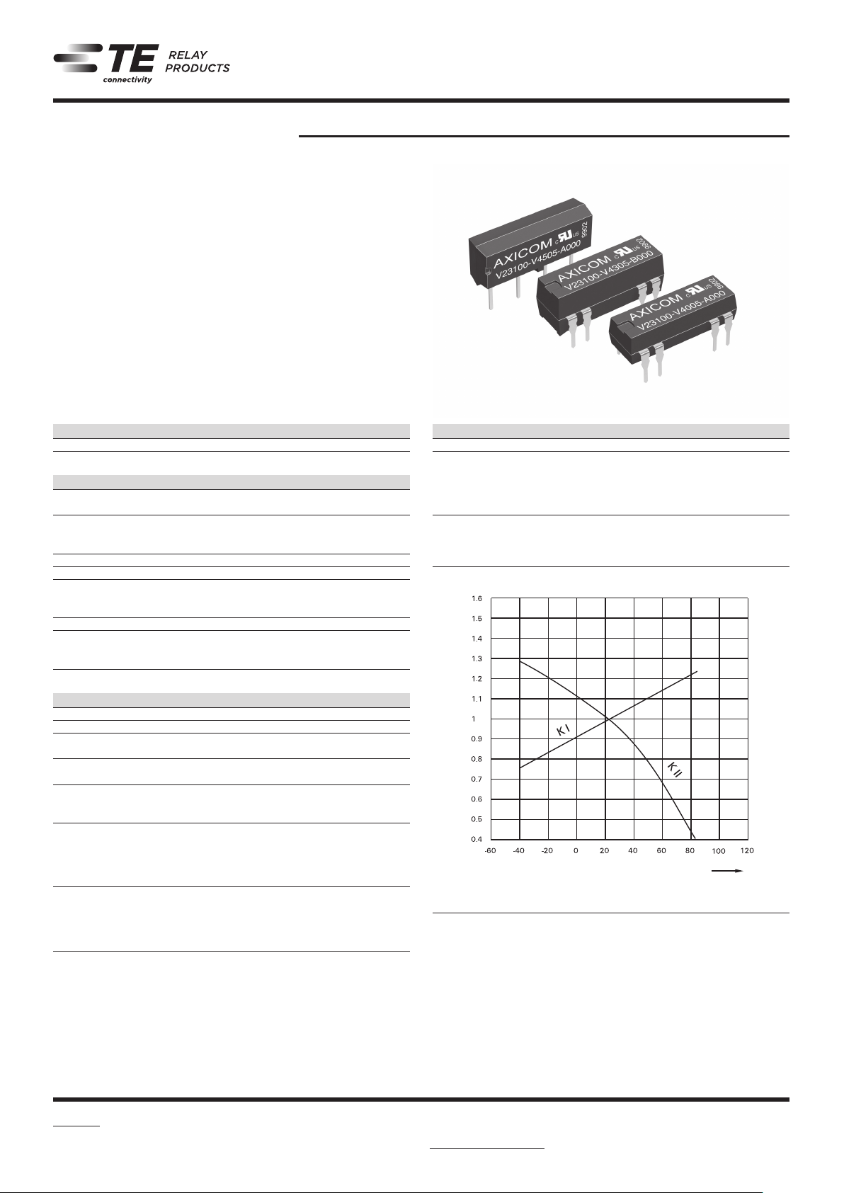
Coil operative range
Coil operative range graphs
U
I
Minimum voltage at 23°C after pre-energizing with rated voltage
without contact current
U
II
Maximum continous voltage at 23°C
The operating voltage limits U
I
and U
II
depend on the temperature according to
the formula:
U
I tamb
K
I
xU
I
23°C and
U
II tamb
K
Il
xU
Il
23°C
tamb Ambient temperature
U
I tamb
Minimum voltage at ambient temperature, tamb
U
II tamb
Maximum voltage at ambient temperature, tamb
K
I
, K
II
Factors (dependent on temperature), see diagram
Reed Relay V23100 -V4
108-98011 Rev. C
All specifications subject to change. Consult Tyco Electronics for latest specifications. 7 of 13
Telecom-, Signal and RF Relays
Reed V23100-V4 Relay
AXICOM
Coil Data (values at 23 °C) Ordering Information
Nominal
voltage
U
nom
Operate/set voltage range Release/
reset voltage
Minimum
Coil
power
Coil
Resistance
Relay
code
Tyco part
number
Minimum
voltage U
min
Maximum
voltage U
max
Vdc Vdc Vdc Vdc mW Ω / ± 10 %
DIP version high: 2 form a contact, standard
5 3.5 14 0.75 125 200 V23100-V4305-B000 1-1393763-8
12 8.4 25 1.80 288 500 V23100-V4312-B000 2-1393763-6
15 10.5 47 2.25 112 2000 V23100-V4315-B000 3-1393763-2
24 16.8 47 3.60 288 2000 V23100-V4324-B000 3-1393763-8
DIP version high: 2 form a contact, with diode
5 3.5 14 0.75 125 200 V23100-V4305-B010 1-1393763-9
12 8.4 25 1.80 288 500 V23100-V4312-B010 2-1393763-7
15 10.5 47 2.25 112 2000 V23100-V4315-B010 3-1393763-3
24 16.8 47 3.60 288 2000 V23100-V4324-B010 3-1393763-9
DIP version high: 1 form c contact, with diode
5 3.5 14.5 0.75 125 200 V23100-V4305-C010 2-1393763-2
12 8.4 23.5 1.80 288 500 V23100-V4312-C010 3-1393763-0
15 10.5 14.5 2.25 112 2000 V23100-V4315-C010 3-1393763-6
24 16.8 49.0 3.60 288 2000 V23100-V4324-C010 4-1393763-2
DIP version high: 1 form c contact, with diode and electrostatic shield
5 3.5 14.5 0.75 125 200 V23100-V4305-C011 2-1393763-3
12 8.4 23.5 1.80 288 500 V23100-V4312-C011 3-1393763-1
15 10.5 14.5 2.25 112 2000 V23100-V4315-C011 3-1393763-7
24 16.8 49.0 3.60 288 2000 V23100-V4324-C011 4-1393763-3
U
I
= Minimum voltage at 23 °C after
preenergizing with nominal
voltage without contact current
U
II
= Maximum continous voltage at 23 °C
The operating voltage limits U
I
and U
II
depend on the
temperature according to the formula:
U
I tamb
= K
I
· U
I 23 °C
and
U
II tamb
= K
Il
· U
Il 23 °C
t
amb
= Ambient temperature
U
I tamb
= Minimum voltage at ambient
temperature, tamb
U
II tamb
= Maximum voltage at ambient
temperature, tamb
k
I
, k
II
= Factors (dependent on temperature),
see diagram
Ambient temperature t
amb
[°C]
Z
器件 Datasheet 文档搜索
AiEMA 数据库涵盖高达 72,405,303 个元件的数据手册,每天更新 5,000 多个 PDF 文件
