Datasheet 搜索 > muRata(村田) > VNH3SP30TR-E 数据手册 > VNH3SP30TR-E 数据手册 1/33 页


¥ 0
VNH3SP30TR-E 数据手册 - muRata(村田)
制造商:
muRata(村田)
Pictures:
3D模型
符号图
焊盘图
引脚图
产品图
页面导航:
引脚图在P6P7Hot
典型应用电路图在P19P20
原理图在P5P6P7
封装尺寸在P29P30P31
封装信息在P31
技术参数、封装参数在P8
电气规格在P8P9P10P11P12P14P15P16P17P18
导航目录
VNH3SP30TR-E数据手册
Page:
of 33 Go
若手册格式错乱,请下载阅览PDF原文件
This is information on a product in full production.
January 2017 DocID12688 Rev 9 1/33
VNH3SP30-E
Automotive fully integrated H-bridge motor driver
Datasheet - production data
Features
AEC-Q100 qualified
Output current: 30 A
5 V logic level compatible inputs
Undervoltage and overvoltage shutdown
Overvoltage clamp
Thermal shut down
Cross-conduction protection
Linear current limiter
Very low standby power consumption
PWM operation up to 10 kHz
Protection against loss of ground and loss of
V
CC
Package: ECOPACK
®
Description
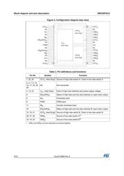
The VNH3SP30-E is a full-bridge motor driver
intended for a wide range of automotive
applications. The device incorporates a dual
monolithic high-side driver (HSD) and two low-
side switches. The HSD switch is designed using
STMicroelectronics proprietary VIPower™ M0-3
technology that efficiently integrates a true Power
MOSFET with an intelligent signal/protection
circuit on the same die.
The low-side switches are vertical MOSFETs
manufactured using STMicroelectronics
proprietary EHD (“STripFET™”) process. The
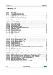
three circuits are assembled in a
MultiPowerSO-30 package on electrically isolated
lead frames. This package, specifically designed
for the harsh automotive environment, offers
improved thermal performance thanks to exposed
die pads. Moreover, its fully symmetrical
mechanical design provides superior
manufacturability at board level. The input signals
IN
A
and IN
B
can directly interface with the
microcontroller to select the motor direction and
the brake condition. Pins DIAG
A
/EN
A
or
DIAG
B
/EN
B
, when connected to an external pull-
up resistor, enable one leg of the bridge. They
also provide a feedback digital diagnostic signal.
The normal operating conditions are explained in
the truth table. The speed of the motor can be
controlled in all possible conditions by the PWM
up to kHz. In all cases, a low level state on the
PWM pin will turn off both the LS
A
and LS
B
switches. When PWM rises to a high level, LS
A
or
LS
B
will turn on again depending on the state of
the input pin.
Type R
DS(on)
I
out
V
ccmax
VNH3SP30-E
45 mmax
per leg)
30 A 40 V
MultiPowerSO-30™
Table 1. Device summary
Package
Order codes
Tape & reel
MultiPowerSO-30 VNH3SP30TR-E
www.st.com
器件 Datasheet 文档搜索
AiEMA 数据库涵盖高达 72,405,303 个元件的数据手册,每天更新 5,000 多个 PDF 文件
