Datasheet 搜索 > 钽电容 > Vishay Sprague > 150D686X9015R2TE3 数据手册 > 150D686X9015R2TE3 其他数据使用手册 1/10 页


¥ 36.787
150D686X9015R2TE3 其他数据使用手册 - Vishay Sprague
制造商:
Vishay Sprague
分类:
钽电容
Pictures:
3D模型
符号图
焊盘图
引脚图
产品图

150D686X9015R2TE3数据手册
Page:
of 10 Go
若手册格式错乱,请下载阅览PDF原文件
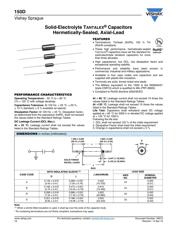
150D
Vishay Sprague
Solid-Electrolyte TANTALEX
®
Capacitors
Hermetically-Sealed, Axial-Lead
www.vishay.com For technical questions, contact: tantalum@vishay.com
Document Number: 40015
18 Revision: 14-Apr-10
FEATURES
• Terminations: Tin/lead (SnPb), 100 % Tin
(RoHS compliant)
• These high performance, hermetically-sealed
T
ANTALEX
®
capacitors have set the standard for
solid-electrolyte tantalum capacitors for more
than three decades.
• High capacitance, low DCL, low dissipation factor and
exceptional operating stability.
• Performance and reliability have been proven in
commercial, industrial and military applications.
• Available in four case codes and capacitors and are
supplied with plastic-film insulation.
• Terminals are solid, tinned nickel wire leads.
• The Military equivalent to the 150D is the M39003/01
(style CSR13) which is qualified to MIL-PRF-39003.
• Compliant to RoHS directive 2002/95/EC
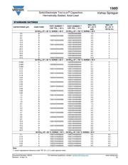
PERFORMANCE CHARACTERISTICS
Operating Temperature: - 55 °C to + 85 °C
(To + 125 °C with voltage derating)
Capacitance Tolerance: At 120 Hz, + 25 °C. ± 20 %,
± 10 % standard. ± 5 % available as special.
Dissipation Factor: At 120 Hz, + 25 °C. Dissipation factor,
as determined from the expression 2πfRC, shall not exceed
the values listed in the Standard Ratings Tables.
DC Leakage Current (DCL Max.):
At + 25 °C: Leakage current shall not exceed the values
listed in the Standard Ratings Tables.
At + 85 °C: Leakage current shall not exceed 10 times the
values listed in the Standard Ratings Tables.
At +125 °C: Leakage shall not exceed 15 times the values
listed in the Standard Ratings Tables.
Life Test: Capacitors shall withstand rated DC voltage
applied at + 85 °C for 2000 h or derated DC voltage applied
at + 125 °C for 1000 h
Following the life test:
1. DCL shall not exceed 125 % of the initial requirement
2. Dissipation Factor shall meet the initial requirement
3. Change in capacitance shall not exceed ± 5 %
Note
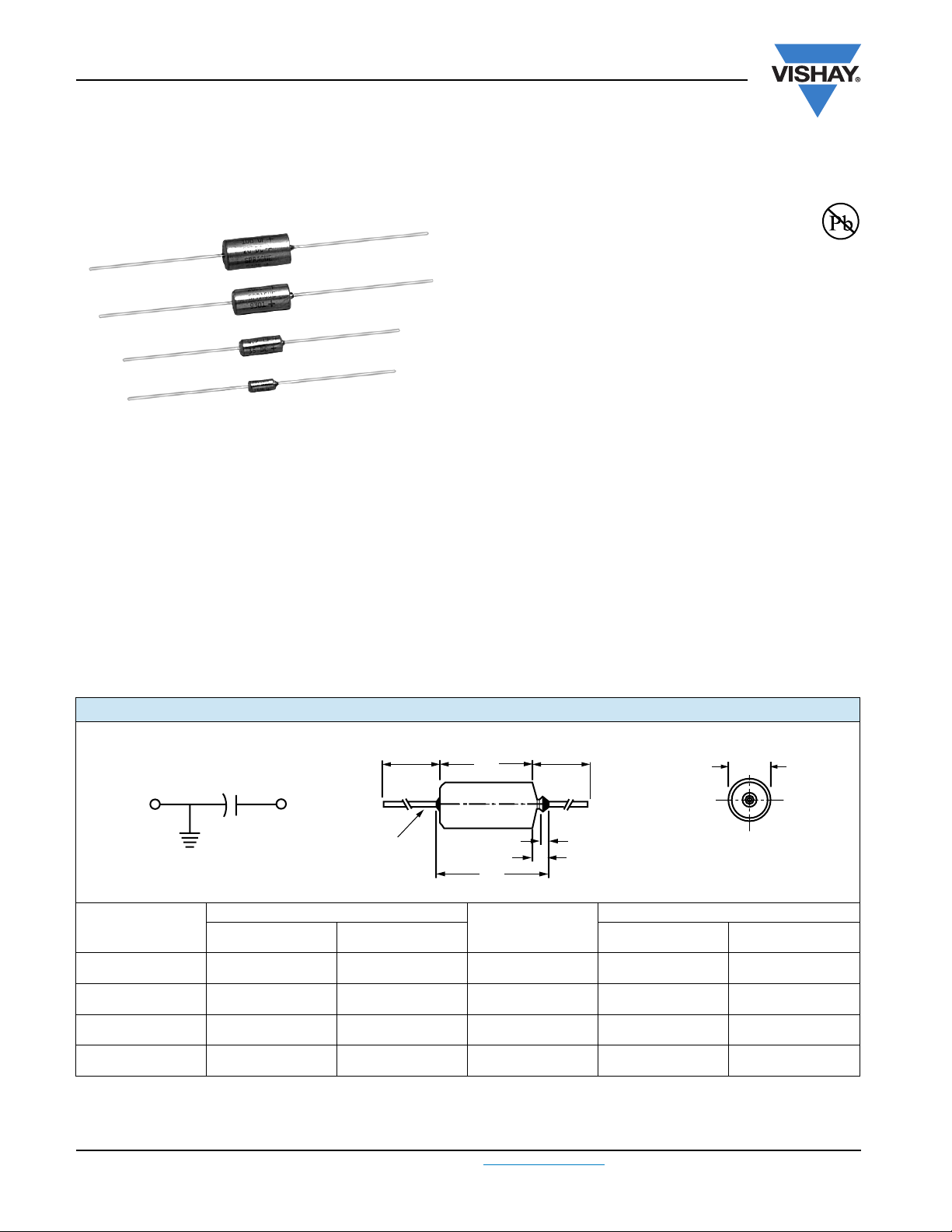
(1)
When a shrink-fitted insulation is used, it shall lap over the ends of the capacitor body
* Pb containing terminations are not RoHs compliant, exemptions may apply
Available
RoHS*
COMPLIANT
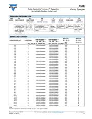
DIMENSIONS in inches [millimeters]
CASE CODE
WITH INSULATING SLEEVE
(1)
J (MAXIMUM)
LEAD SIZE
D L
AWG
NO.
NOMINAL
DIAMETER
A
0.135 ± 0.016
[3.43 ± 0.41]
0.286 ± 0.031
[7.26 ± 0.79]
0.422
[10.720]
24
0.020
[0.51]
B
0.185 ± 0.016
[4.70 ± 0.41]
0.474 ± 0.031
[12.04 ± 0.79]
0.610
[15.490]
24
0.020
[0.51]
R
0.289 ± 0.016
[7.34 ± 0.41]
0.686 ± 0.031
[17.42 ± 0.79]
0.822
[20.880]
22
0.025
[0.64]
S
0.351 ± 0.016
[8.92 ± 0.41]
0.786 ± 0.031
[19.96 ± 0.79]
0.922
[23.420]
22
0.025
[0.64]
0.125 [3.18] MAX.
SOLID TINNED
NICKEL LEADS
L
J
MAX..
D
DIA.
1.500 ± 0.250
[38.10 ± 6.35]
1.500 ± 0.250
[38.10 ± 6.35]
0.047 [1.19] MAX.
-
+
器件 Datasheet 文档搜索
AiEMA 数据库涵盖高达 72,405,303 个元件的数据手册,每天更新 5,000 多个 PDF 文件
