Datasheet 搜索 > 齐纳二极管 > Microsemi(美高森美) > 1N5349AE3/TR8 数据手册 > 1N5349AE3/TR8 其他数据使用手册 1/3 页


¥ 13.949
1N5349AE3/TR8 其他数据使用手册 - Microsemi(美高森美)
制造商:
Microsemi(美高森美)
分类:
齐纳二极管
封装:
T-18-2
Pictures:
3D模型
符号图
焊盘图
引脚图
产品图

1N5349AE3/TR8数据手册
Page:
of 3 Go
若手册格式错乱,请下载阅览PDF原文件
Summer 1997
12
MicroNote
Series 205
by Kent Walters, Microsemi Scottsdale
Zero-Temperature
Coefficient
Reference Diodes
In MicroNotes 203, zeners were
described with their characteristic
positive temperature coefficient α
VZ
(or TC herein) for nominal voltages
exceeding five volts. In sensitive
applications requiring a precision
voltage reference in varying
temperature environments, a near
zero TC is of significant value in
tightly controlling voltage beyond
what a zener can provide by itself.
Special zener diodes that are
further designed to have extremely
low TC have been identified as
zero-TC reference diodes or simply
reference diodes.
Reference diodes are made
possible by combining the
described positive TC of the zener
in series with one or more forward
biased p-n junctions that display a
negative TC. Each forward biased
p-n junction typically contributes a
negative TC of -2 mV/°C. As seen
in MicroNote 203, the zener TC
progressively increases in positive
magnitude as zener diode voltage
nominals increase above five volts.
Since negative or positive TC
characteristics of forward or zener
biased diodes are approximately
linear with increasing temperature,
they can be judiciously combined
into several series combinations for
near zero TC performance. The
voltage of this reference diode
configuration also becomes the
sum total of the zener voltage and
the added forward voltages with p-n
or n-p junctions.
Reference diodes are a very
mature product in packages such
as DO-7 and DO-35 JEDEC
registered outlines. More recently
they have also become available in
surface mount configurations such
as the DO-213AA or AB outlines
often called MELFs. These
packages are typically rated in the
400 to 500 mW range since their
application is not for significant
power dissipation. This is
adequate for applied power up
to100 mW when operated at rated
test currents I
ZT
of 7.5 mA with
voltage nominals up to 11.7 volts.
These conservative operating power
levels then allow required power
derating from 400 or 500 mW for an
elevated operating temperature
range as high as 150°C while
providing near zero TC reference
voltage performance at I
ZT
. Zero-TC
reference diodes are usually rated
in effective TC performance by
percent change of nominal V
Z
per
degree C (%/°C) or mV change
over a defined temperature range.
Within a reference diode product
family, this often starts at ±0.01 %/
°C and can go as low as ±0.0002
%/°C in some examples. All of
these TC values are significantly
less than the zener voltage
regulator element by itself which
can be as high as +0.1 %/°C.
The TC (or α
VZ
) is most often
stated in terms of what has
historically been called the “box
method”. This simply defines a
ratio in maximum specified voltage
change ∆V
Z
expressed in
percentage of nominal V
Z
divided
by the overall operating
temperature range or ∆T. It has
been further defined in many
JEDEC and military specs to
include specific temperature points
for standardized testing such as -
55°C, 0°C, 25°C, 75°C, 100°C, and
150°C. These are also dependent
on overall temperature range
specified in TC for the reference
diode. When testing these
specific temperatures, the greatest
voltage change ∆V
Z
can occur
between any two temperatures
rather than just temperature
extremes (thus the box method).
This suggests TC (or α
VZ
) can also
be nonlinear despite being
expressed in terms of %/°C.
Nonlinear characteristics are only
recognized easily on tight
tolerance zero-TC reference diodes
of 0.001%/°C or less. In such
examples, voltage change is
sufficiently small over a wide
temperature range to observe this
possible characteristic.
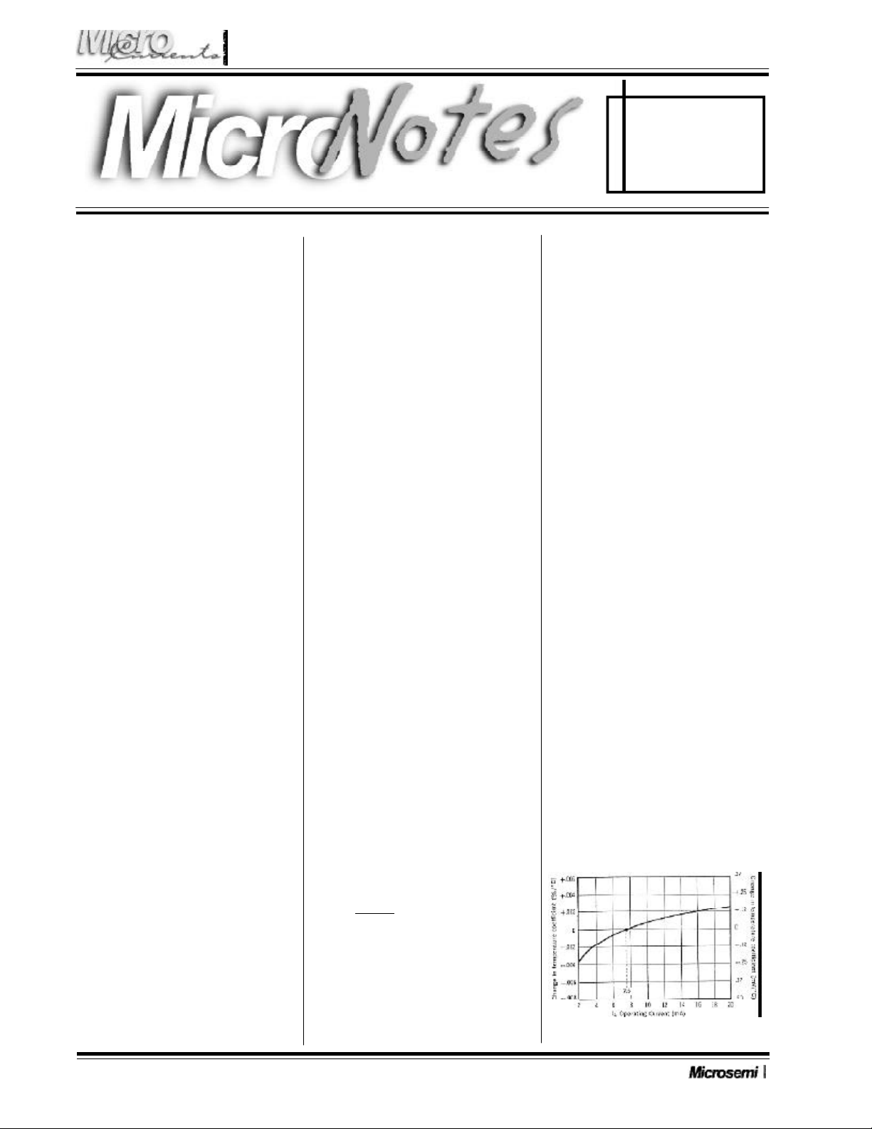
Since the TC of reference diodes
with forward compensating
elements are affected by operating
current, it is important to operate
them at or very near their specified
test current I
ZT
compared to
conventional zener diodes (see
MicroNote 201). This is an
important added operating
condition to achieve rated TC
performance for reference diodes.
If operating current exceeds I
ZT
, the
TC will shift in a positive direction
compared to that observed at I
ZT
. If
operated below the I
ZT
, it will shift
negative in TC. An example
response curve for the popular
1N821 to 1N829 series for TC
versus operating current when
Figure 1: Typical change of temperature coefficient with
change in operating current for 1N821 thru 1N829
器件 Datasheet 文档搜索
AiEMA 数据库涵盖高达 72,405,303 个元件的数据手册,每天更新 5,000 多个 PDF 文件
