Datasheet 搜索 > 放大器、缓冲器 > ADI(亚德诺) > AD8273ARZ 数据手册 > AD8273ARZ 其他数据使用手册 5/9 页
 器件3D模型
¥ 12.846
AD8273ARZ 其他数据使用手册 - ADI(亚德诺)
制造商:
ADI(亚德诺)
分类:
放大器、缓冲器
封装:
SOIC-14
描述:
ANALOG DEVICES AD8273ARZ 差分放大器, 2 放大器, 2 dB, 20000 kHz, -40 °C, 85 °C
Pictures:
3D模型
符号图
焊盘图
引脚图
产品图
页面导航:
典型应用电路图在P1
原理图在P1
导航目录
AD8273ARZ数据手册
Page:
of 9 Go
若手册格式错乱,请下载阅览PDF原文件
Application Note AN-1328
+
6
3
8
7
5
2
1
4
VIN
ADP1613
ADP1720
EN
SS
FREQ
2
5
IN OUT
EN
1
ADJ
GND
6
GND
7
GND
8
GND
GND
SW
FB
COMP
3
4
1.0µF
1.0µF
1.0µF
1.0µF
1.0µF 1.0µF
1.0µF
5.1V
1.0µF
47µH
47µH
1 2
4 3
4 3
1
C
3
1
2
B
E
2
10µF
–9V
+9V
10µF
+
+
VBATT
VBATT
+1.8V SUPPLY
AVDD
1.0µF
47.0kΩ
21.5kΩ
71.5kΩ
11.3kΩ
5.36kΩ
10nF 100pF
0Ω
±9V SUPPLY
169Ω121kΩ
10907-008
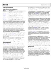
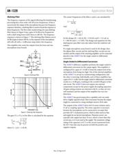
Figure 8. Details of Power Supply Circuit
±9 V Power Supply
All of the amplifiers in this design are powered from ±9 V supplies.
These voltages are generated from an ADP1613 in a SEPIC-Ćuk
configuration. This circuit generates the positive and negative
supply rails from a single input voltage as shown in Figure 8.
The design for the bipolar supply design was created using the
ADIsimPower™ tools. The ADP161x SEPIC-Ćuk Design Tool takes
some basic design parameters as an input and generates a
schematic, bill of materials (BOM), and performance specifications
for the given circuit. This design was created using the following
specifications:
• V
IN
minimum = 7.5 V
• V
IN
maximum = 9.0 V
• V
OUT
= 9.0 V
• I
OUT
= 40 mA
• Ambient temperature = 55°C
• Design optimized for lowest cost
The total current drawn from the battery when the complete system
is operational is 82 mA. Of this total current, about 17.5 mA is used
by each microphone board, and 47 mA is used by the power board.
With this load, a typical 9 V battery lasts about five hours.
1.8 V Power Supply
The 1.8 V supply is used to power the ADMP411 MEMS
microphones and is generated from the ADP1720 linear regulator.
This regulator drops the regulated +9 V supply to the necessary
1.8 V in a very small printed circuit board (PCB) footprint,
requiring only one small (1 μF) bypass capacitor, on both the
input and the output, and two resistors to set the output voltage.
The ADMP411 draws a maximum current of 220 μA with a
1.8 V supply, so the highest current needed from this regulator
output (with 32 ADMP411 devices connected) is 7.04 mA. At
this maximum load, the regulator dissipates 50.7 mW:
P = (9 V – 1.8 V) × 7.04 mA = 50.7 mW
ADDITIONAL CIRCUITRY
This section describes the function of additional components
that are used in the circuit but are not part of the core circuit
design. This primarily includes RF filtering and overvoltage
protection circuitry
RF Filtering
Between the differential output of the AD8273 devices and the
XLR plug, there are a few components intended to filter high
frequency noise that may be picked up by the board or the
microphone XLR cable. Each half of the differential signal has
an LC filter, which removes electromagnetic interference (EMI)
or RF noise. There is also a common-mode choke between the two
differential legs to remove common-mode currents, while allowing
differential currents to pass.
The connection of the microphone signals between the
microphone boards and the power board also has an LC filter to
reduce high frequency noise that may be picked up by the
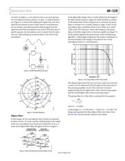
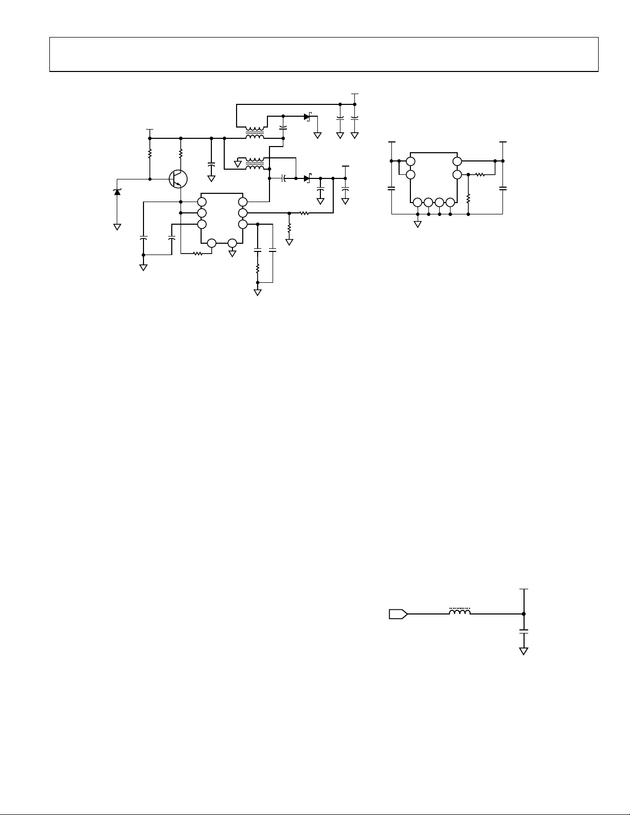
ribbon cable connection. A similar LC filter (see Figure 9) is
also used on the output of all of the regulated voltage supplies.
SUPPLY
VOLT
AGE
REGULATOR
OUTPUT
1800Ω AT 100MHz
1.0nF
10907-009
Figure 9. RF Noise Filter
Spike Suppression
Back to back 5.1 V Zener diodes are connected between each
side of the differential output signal and ground. These diodes
are used to clamp voltage spikes greater than ±5.1 V that may be
conducted on the output cable.
Rev. A | Page 5 of 9
器件 Datasheet 文档搜索
AiEMA 数据库涵盖高达 72,405,303 个元件的数据手册,每天更新 5,000 多个 PDF 文件
