Datasheet 搜索 > 稳压芯片 > Intersil(英特矽尔) > ISL6217CVZ 数据手册 > ISL6217CVZ 其他数据使用手册 5/19 页

 器件3D模型
¥ 36.162
ISL6217CVZ 其他数据使用手册 - Intersil(英特矽尔)
制造商:
Intersil(英特矽尔)
分类:
稳压芯片
封装:
TSSOP-38
描述:
精密多相降压PWM精密多相降压PWM定位IMVP- IVA ?? ¢和IMVP -IV Precision Multi-Phase Buck PWM Precision Multi-Phase Buck PWM Positioning IMVP-IV⢠and IMVP-IV
Pictures:
3D模型
符号图
焊盘图
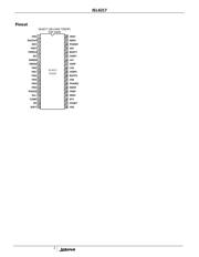
引脚图
产品图
页面导航:
导航目录
ISL6217CVZ数据手册
Page:
of 19 Go
若手册格式错乱,请下载阅览PDF原文件
ISL6217
5
Absolute Voltage Ratings
Supply Voltage, VDD, VDDP.....................................-0.3-+7V
Battery Voltage, VBAT....................................................+30V
Boot1,2 and UGATE1,2..................................................+35V
Phase1,2 and ISEN1,2...................................................+30V
Boot1,2 with respect to Phase1,2..................................+6.5V
UGATE1,2 ...................(Phase1,2 - 0.3V) to (Boot1,2 + 0.3V)
PHASE 1,2 Voltage..............GND- 0.3V (DC) to V
BOOT
+ 0.3V
...........GND - 5V (<100ns Pulse Width, 10µJ) to V
BOOT
+ 0.3V
ALL OTHER PINS ............................... -0.3V to (VDD + 0.3V)
Recommended Operating Conditions
Supply Voltage, VDD, VDDP....................................+5V ±5%
Battery Voltage, VBAT........................................+5.6V to 25V
Ambient Temperature.......................................-10°C to 85°C
Junction Temperature.....................................-10°C to 125°C
Thermal Information
Thermal Resistance (Typical, Note 1) θ
JA
(
o
C/W)
TSSOP Package (Note 1) ................................................ 72°
Maximum Operating Junction Temperature ..................125
o
C
Maximum Storage Temperature Range ..........-65
o
C to 150
o
C
Maximum Lead Temperature (Soldering 10s)...............300
o
C
CAUTION: Stress above those listed in “Absolute Maximum Ratings” may cause permanent damage to the device. This is a stress only rating and
operation of the device at these or any other conditions above those indicated in the operational section of this specification is not implied.
NOTE:
1) θ
JA
is measured with the component mounted on a high effective thermal conductivity test board in free air.
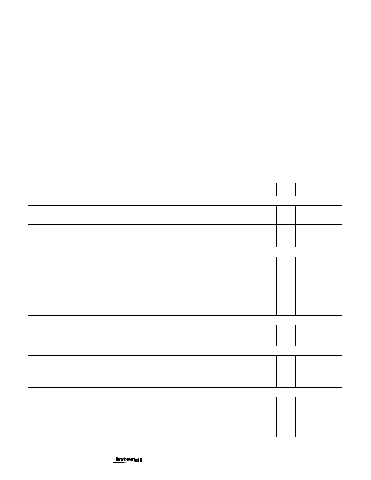
Electrical Specifications Operating Conditions: VDD = 5V, TA = -10°C to 85°C, Unless Otherwise Specified
PARAMETER TEST CONDITIONS MIN TYP MAX UNITS
INPUT POWER SUPPLY
EN = 3.3V, DSEN# = 0, DRSEN = 0, PWRCH = 0 - 1.4 - mA
Input Supply Current, I(VDD)
EN = 0V - 1 - µA
V
DD
Rising 4.35 4.45 4.5 V
POR (Power-On Reset) Threshold
V
DD
Falling 4.05 4.20 4.40 V
REFERENCE AND DAC
System Accuracy Percent system deviation from programmed VID Codes @ 1.356 -0.8 - 0.8 %
DAC (VID0 - VID5) Input Low
Voltage
DAC Programming Input Low Threshold Voltage - - 0.3 V
DAC (VID0 - VID5) Input High
Voltage
DAC Programming Input High Threshold Voltage 0.7 - - V
Maximum Output Voltage - 1.708 - V
Minimum Output Voltage - 0.70 - V
CHANNEL GENERATOR
Frequency, F
SW
R
Fset
= 243K, ±1% 225 250 275 kHz
Adjustment Range 0.25 - 1.0 MHz
ERROR AMPLIFIER
DC Gain - 100 - dB
Gain-Bandwidth Product C
L
= 20pF - 18 - MHz
Slew Rate C
L
= 20pF - 4.0 - V/µs
ISEN
Full Scale Input Current - 32 - µA
Overcurrent Threshold R
OCSET
=124K - 64 - µA
Soft Start Current SOFT = 0V - 31 - µA
Droop Current ISEN = 32µA 26.5 28 29.5 µA
GATE DRIVER
器件 Datasheet 文档搜索
AiEMA 数据库涵盖高达 72,405,303 个元件的数据手册,每天更新 5,000 多个 PDF 文件
