Datasheet 搜索 > 微控制器 > Microchip(微芯) > PIC10F222T-I/OT 数据手册 > PIC10F222T-I/OT 产品描述及参数 1/4 页

¥ 3.164
PIC10F222T-I/OT 产品描述及参数 - Microchip(微芯)
制造商:
Microchip(微芯)
分类:
微控制器
封装:
SOT-23-6
描述:
MICROCHIP PIC10F222T-I/OT 微控制器, 8位, 闪存, AEC-Q100, PIC10F2xx, 8 MHz, 768 Byte, 23 Byte, 6 引脚, SOT-23
Pictures:
3D模型
符号图
焊盘图
引脚图
产品图
PIC10F222T-I/OT数据手册
Page:
of 4 Go
若手册格式错乱,请下载阅览PDF原文件
2004 Microchip Technology Inc. DS91083A-page 1
TB083
INTRODUCTION
The PIC10F204/206 microcontrollers have a built-in
comparator which can be utilized to detect different
discrete voltage levels. This technical brief describes
one technique for detecting two or more such voltages
as different trip points.
THEORY
This technique takes advantage of the properties of an
RC network. An RC network, which is charged up to a
known voltage, will have a voltage decay governed by
an RC time constant, as shown in Equation 1.
EQUATION 1:
If the voltages and values of R and C are known, then
the time t may be determined by re-evaluating the
equation shown in Equation 2.
EQUATION 2:
By knowing the time required for a given VOUT, a look-
up table, (see AN556, “Implementing A Table Read”), in
firmware, equates a given time to a given voltage.
Using discrete times of interest, trip points are created
which a microcontroller acts upon.
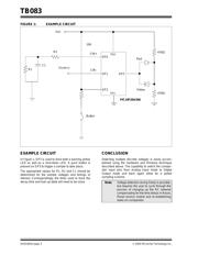
HARDWARE TECHNIQUE
Pins GP0/CIN+ and GP1/CIN-, of the PIC10F204/206
microcontrollers, can be switched between Digital
mode and Analog mode under firmware control. By
placing a known RC network on GP0/CIN+ and the
voltage to be sampled on GP1/CIN-, firmware can
detect discrete voltages.
Application firmware sets pin GP0/CIN+ to Digital mode
and applies a PWM signal to the pin to charge up the
RC network to a known voltage higher than the sample
voltage to be detected. Once the RC network is
charged, pin GP0/CIN+ is switched to Analog mode
and a comparator read made. By starting a timer and
keeping track of the time interval for the comparator to
trip, a time is determined which can be referenced to a
look-up table in firmware for various voltage values.
The size of the look-up table should be adjusted to
cover the voltage regions of interest.
Application firmware will take different actions at
different trip points such as providing a warning and
then a shutdown.
In order to switch pin GP0/CIN+ from Analog mode to
Digital mode and back again, use the CMPON control
bit in the CMCON0 register (CMCON0<3>). By turning
the comparator on, the pin is set to Analog mode. By
turning the comparator off, the pin is set to Digital
mode.
Author: Roy Sasaki
Michael Waldron
Microchip Technology Inc.
VOUT = VIN *
e
-t/RC
VOUT = Volts, R = Ohms, t = Seconds, VIN = Volts,
C = Farads
t = -1*RC * In (VOUT/VIN)
Note: The sampled voltage is assumed to be
stable during the sampling period. Users
should setup their firmware and look-up
tables to search for time ranges rather
than exact time intervals to adjust for
sample voltages which drift.
Detecting Multiple Voltages Using the
PIC10F204/206 Comparator
器件 Datasheet 文档搜索
AiEMA 数据库涵盖高达 72,405,303 个元件的数据手册,每天更新 5,000 多个 PDF 文件
