Datasheet 搜索 > 铝电解电容 > Nichicon(尼吉康) > UUD1H101MNL1GS 数据手册 > UUD1H101MNL1GS 其他数据使用手册 1/3 页
 器件3D模型
¥ 1.99
UUD1H101MNL1GS 其他数据使用手册 - Nichicon(尼吉康)
制造商:
Nichicon(尼吉康)
分类:
铝电解电容
封装:
SMD
描述:
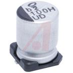
NICHICON UUD1H101MNL1GS 铝电解电容, 表面贴装, UD系列, 100 µF, 50 V, Radial Can - SMD, 8 mm
Pictures:
3D模型
符号图
焊盘图
引脚图
产品图
页面导航:
标记信息在P1P2P3
封装信息在P3
技术参数、封装参数在P1P2P3
电气规格在P1P2P3
导航目录
UUD1H101MNL1GS数据手册
Page:
of 3 Go
若手册格式错乱,请下载阅览PDF原文件
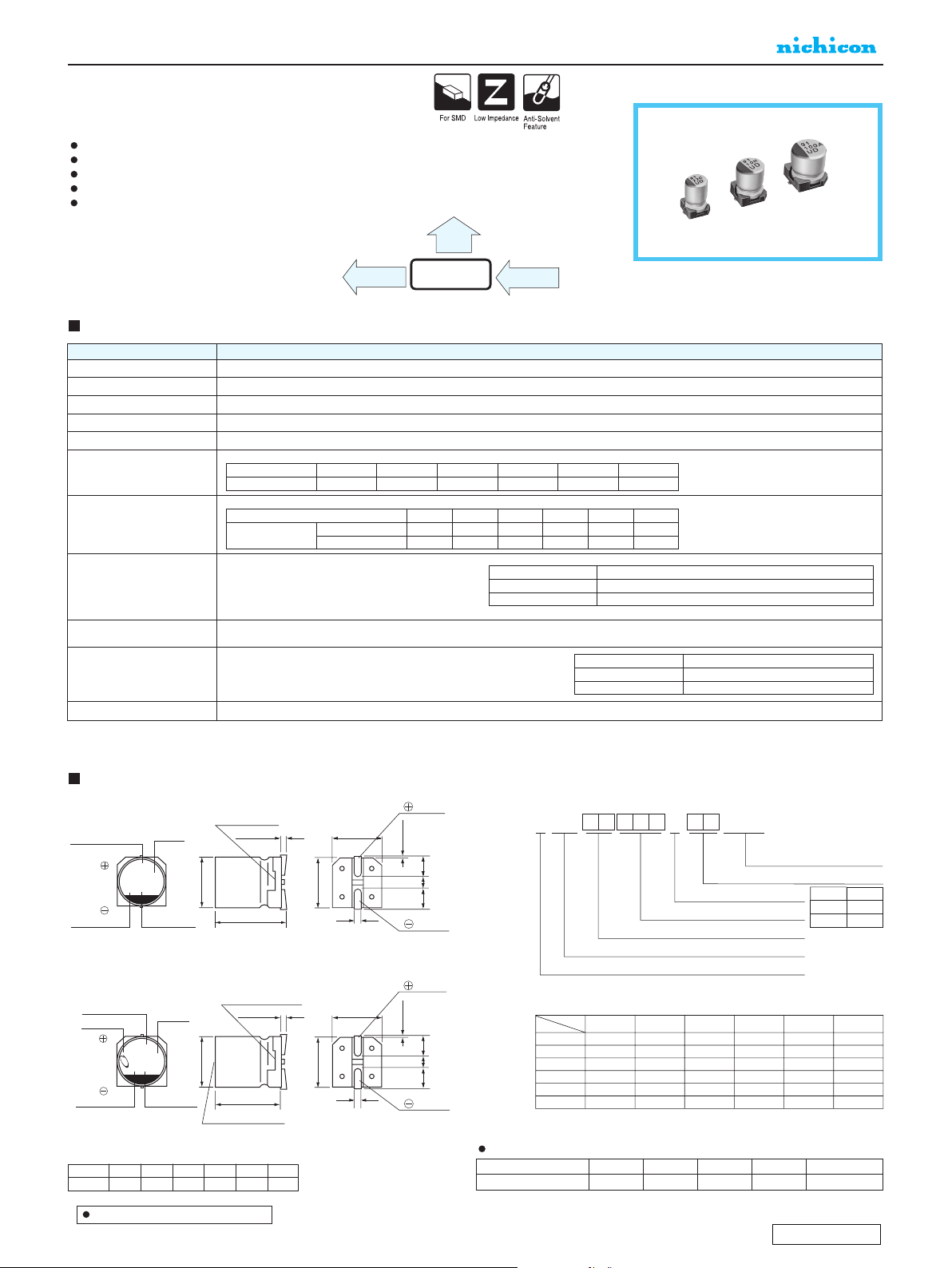
ALUMINUM ELECTROLYTIC CAPACITORS
P.17
CAT.8100J
Frequency coefficient of rated ripple current
Coefficient
Frequency
50 Hz 120 Hz 300 Hz 1 kHz 10 kHz or more
0.35 0.50 0.64 0.83 1.00
A2
22C
UD
A2
100V
UD
0.3MAX.
φD±0.5
B±0.2
A±0.2A±0.2
C±0.2
0.5MAX.
E
H
H
0.3MAX.
φD±0.5
B±0.2
A±0.2A±0.2
C±0.2
0.5MAX.
E
L±0.3
L±0.5
Series
Capacitance
Lot No.
Lot No. Capacitance
Plastic platform
Plastic platform
Series
Trade mark
Voltage (C:16V)
Voltage (V:35V)
Negative
Positive
Negative
Positive
Pressure relief vent
U
1
U
2
D
3
1
4
C
5
2
6
2
7
0
8
M
9
C
10
L
11
1
12
G
13
S
14
φ
D
4 to 6.3
8
•
10
CL
NL
Configuration
Taping code
Capacitance tolerance (±20%)
Rated capacitance (22µF)
Rated voltage (16V)
Series name
Type
Code
(mm)
A
B
C
E
L
H
4 × 5.8
1.8
4.3
4.3
1.0
5.8
0.5 to 0.8
5 × 5.8
2.1
5.3
5.3
1.3
5.8
0.5 to 0.8
6.3 × 5.8
2.4
6.6
6.6
2.2
5.8
0.5 to 0.8
6.3 × 7.7
2.4
6.6
6.6
2.2
7.7
0.5 to 0.8
8 × 10
2.9
8.3
8.3
3.1
10
0.8 to 1.1
10 × 10
3.2
10.3
10.3
4.5
10
0.8 to 1.1
φ D × L
UUD
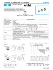
Chip Type, Low Impedance
Chip type, low impedance temperature range up to +105
°C
.
Designed for surface mounting on high density PC board.
Applicable to automatic mounting machine fed with carrier tape.
Compliant to the RoHS directive (2011/65/EU,(EU)2015/863).
AEC-Q200 compliant. Please contact us for details.
Chip Type
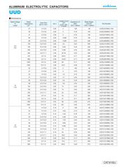
Specifications
Category
Temperature Range
Rated
Voltage Range
Rated
Capacitance Range
Capacitance Tolerance
Leakage Current
Tangent of loss angle (tan δ)
Stability at Low Temperature
Endurance
Shelf Life
Resistance to soldering
heat
Marking
Performance Characteristics
Item
–55 to +105°C
6.3 to 50V
1 to 1500µF
± 20% at 120Hz, 20°C
After 2 minutes' application of rated voltage at 20°C, leakage current is not more than 0.01 CV or 3 (µA), whichever is greater.
Black print on the case top.
The specifications listed at right shall be met
when the capacitors are restored to 20°C after the
rated voltage is applied for 5000 hours (2000
hours for
φD = 4, 5 and 6.3) at 105°C.
After storing the capacitors under no load at 105°C for 1000 hours and then performing voltage treatment based on JIS C 5101-4
clause 4.1 at 20°C, they shall meet the specified values for the endurance characteristics listed above.
Type numbering system (Example : 16V 22
µ
F)
Measurement frequency : 120Hz at 20°C
Measurement frequency : 120Hz
( ) is φ8 over
Z–25°C / Z+20°C
Z
–
55°C / Z+20°C
Rated voltage (V)
Impedance ratio
ZT / Z20 (MAX.)
16
2
4
10
2
4
6.3
3
5
25
2
3
35
2
3
50
2
3
Rated voltage (V)
tan δ (MAX.)
50
0.12 (0.14)
35
0.12 (0.14)
25
0.14 (0.16)
16
0.16 (0.20)
10
0.20 (0.24)
6.3
0.26 (0.28)
Within ±30% of the initial capacitance value
Less than or equal to the initial specified value
200% or less than the initial specified value
Capacitance change
tan δ
Leakage current
Capacitance change
Leakage current
tan δ
Within ±10% of the initial capacitance value
Less than or equal to the initial specified value
Less than or equal to the initial specified value
The capacitors are kept on a hot plate for 30 seconds, which is
maintained at 250°C. The capacitors shall meet the characteristic
requirements listed at right when they are removed from the plate
and restored to 20°C.
(φ4 to φ6.3)
(φ8,φ10 )
Dimension table in next page.
Voltage
V 6.3 10 16 25 35 50
Code
j
A C E V H
UUD
UWG
Low ImpedanceLow Impedance
UCD
UWD
High
Temp reflow
ALUMINUM ELECTROLYTIC CAPACITORS
P.171
CAT.8100J
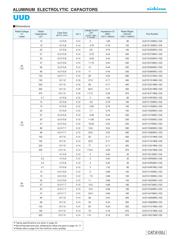
UUD
φ
δ
.
1
11
P
.3
7 . . 3 1. 71
33 . . 3 .7 1 331
7 . . 3 .7 1 71
. . 3. .7 1 1
.3. . . . 3 1
1 .3. . .3 . 3 111
1 .3. . . . 3 111
.3. . 13. . 3 11
33 .37.7 . .7 .3 3311
7 1 . .1 .17 711
1 . . .17 11
1 1 . 3 .17 11
1 11 . . . 7 11
1
1
. . 3 1. 11
7 . . 3 .7 1 171
33 . . 3.3 .7 1 1331
7 .3. . .7 . 3 171
.3. . . . 3 11
.3. . . . 3 11
1 .3. . 1 . 3 1111
1 .3. . 1 . 3 1111
.37.7 . .3 111
33 1 . 33 .17 13311
7 1 . 7 .17 1711
11 . . 7 111
1 11 . 1 . 7 111
1
1
1 . .1 3 1. 111
. .1 3. .7 1 11
7 . .1 .3 .7 1 171
33 .3. .1 . . 3 1331
7 .3. .1 7. . 3 171
.3. .1 . . 3 11
.3. .1 1. . 3 11
1 .3. .1 1 . 3 1111
1 .37.7 .1 .3 1111
.37.7 .1 3. .3 111
33 1 . . .17 13311
7 1 . 7. .17 1711
11 . 1. . 7 111
Dimensions
器件 Datasheet 文档搜索
AiEMA 数据库涵盖高达 72,405,303 个元件的数据手册,每天更新 5,000 多个 PDF 文件
