Datasheet 搜索 > 接口芯片 > ADI(亚德诺) > ADM3491AR-REEL7 数据手册 > ADM3491AR-REEL7 产品设计参考手册 5/12 页

 器件3D模型
¥ 7.239
ADM3491AR-REEL7 产品设计参考手册 - ADI(亚德诺)
制造商:
ADI(亚德诺)
分类:
接口芯片
封装:
SOIC-14
描述:
3.3 V摆率限制,半双工和全双工, RS - 485 / RS -422收发器 3.3 V Slew Rate Limited, Half- and Full-Duplex, RS-485/RS-422 Transceivers
Pictures:
3D模型
符号图
焊盘图
引脚图
产品图
页面导航:
应用领域在P1P9
电气规格在P9
导航目录
ADM3491AR-REEL7数据手册
Page:
of 12 Go
若手册格式错乱,请下载阅览PDF原文件
APPLICATION NOTE AN-960
Rev. 0 | Page 5 of 12
()
TERMINATION
In a transmission line, there are two wires, one to carry the
currents from the driver to the receiver and another to provide
the return path back to the driver. RS-485 links are a little more
complicated because of the fact that they have two signal wires
that share a termination as well as a ground return path.
However, the basic principles of transmission lines are the same.
For reliable RS-485 and RS-422 communications, it is essential
that the reflections in the transmission line be kept as small as
possible. This can only be done by proper cable termination.
Reflections happen very quickly during and just after signal
transitions. On a long line, the reflections are more likely to
continue long enough to cause the receiver to misread logic
levels. On short lines, the reflections occur much sooner and
have no effect on the received logic levels.
In RS-422 applications there is only one driver on the bus and
if termination is to be used it must be placed at the end of the
cable near the last receiver. RS-485 applications require termin-
ation at the master node and the slave node furthest from the
master. Table 2 shows a comparison of different termination
techniques.
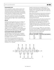
No Termination
The time required for a signal to propagate down the line to a
receiver determines if a line is considered a transmission line.
Physically long wires have longer propagation times, whereas
physically short wires have shorter propagation times. When
the propagation time is short relative to the data bit duration,
the effect on the signal quality is minimized. A cable is not seen
as a transmission line if the signal rise time is more than four
times the propagation delay of the cable.
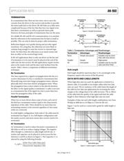
Parallel Termination
When two or more drivers share a pair of wires, each end of
the link has a termination resistor equal to the characteristic
impedance of the cable. There should be no more than two
terminating resistors in the network regardless of how many
nodes are connected.
In a half-duplex configuration, both ends of the cable must be
terminated (see Figure 3). In a full duplex configuration only
the master receiver and most remote slave receiver need to be
terminated.
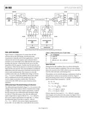
AC Termination
AC termination is used to reduce the power consumption of
idle links as well as to reduce ringing voltages. The negative
effect though is a reduction in cable length and bit rate. A
resistor and capacitor can be placed in series across the bus
(between A and B) as shown in Figure 5. The Capacitor C
T
is
selected by using the following formula:
(ps))2(
(pF)C
T
ancestic ImpedCharacteri
ble DelayOne-Way Ca
>
B
A
DI
RO
RE
07395-005
R
T
DIFFERENTI
A
L
DRIVER
DIFFERENTI
A
L
RECEIVER
Figure 5. Parallel Termination
B
A
DI
RO
RE
07395-006
R
T
C
T
DIFFERENTI
A
L
DRIVER
DIFFERENTI
A
L
RECEIVER
Figure 6. AC Termination
Table 2. Termination Advantages and Disadvantages
Termination Advantages Disadvantages
None Simple, low power
Suitable only for short
links with slow drivers
Parallel Simple High power
AC Low power
Suitable only for low bit
rates and short links
Stub Length
Stub length should be much less than ¼ of a wavelength of the
frequency equal to the inverse of the bit period.
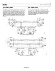
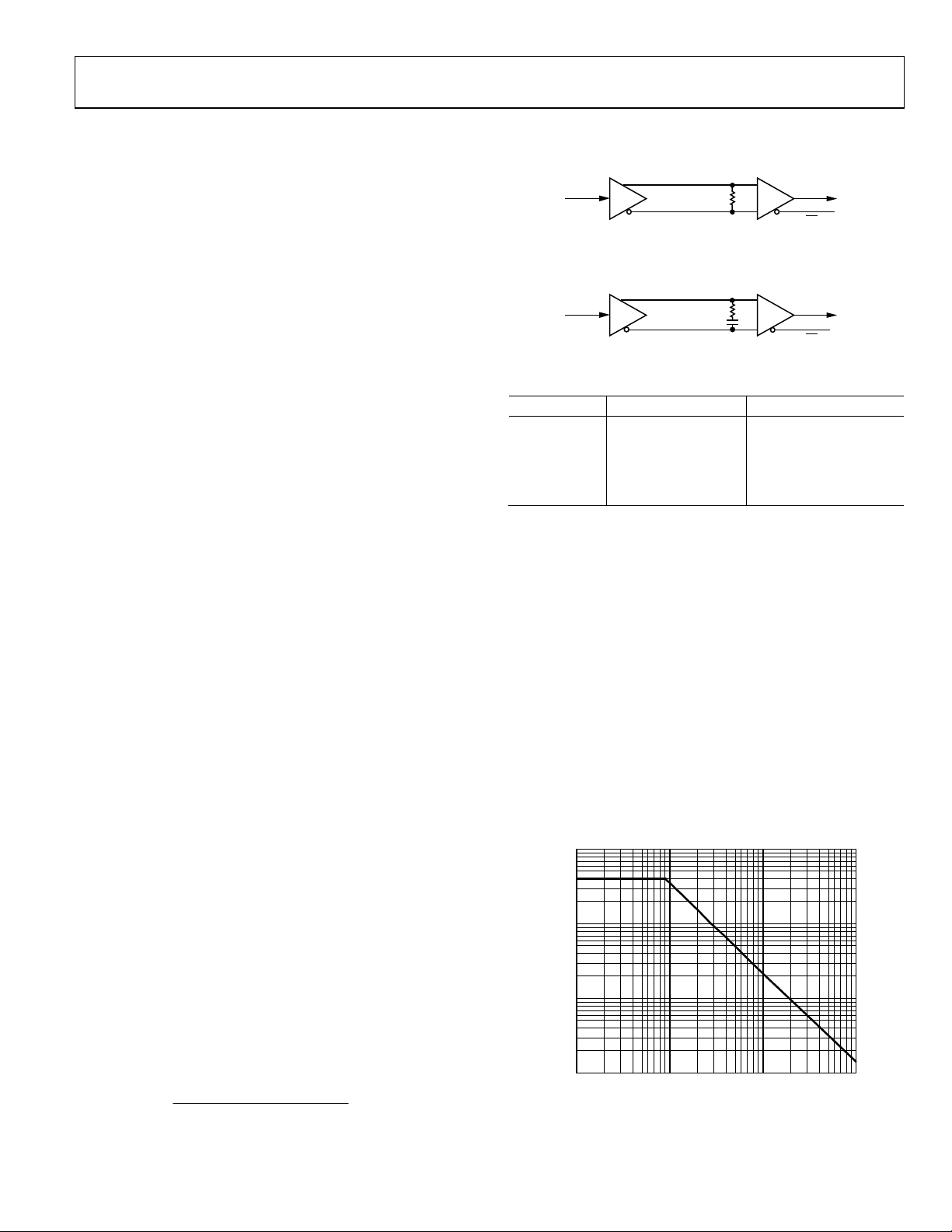
DATA RATE AND CABLE LENGTH
When high data rates are used, the application is limited to a
shorter cable. It is possible to use longer cables when low data
rates are used. The dc resistance of the cable limits the length of
the cable for low data rate applications by increasing the noise
margin as the voltage drop in the cable increases. The ac effects
of the cable limit the quality of the signal and limit the cable
length to short distances when high data rates are used.
Examples of data rate and cable length combinations vary from
90 kbps at 4000 feet to 10 Mbps at 15 feet for RS-422.
Figure 7 can be used as a conservative guide for cable length vs.
data rate.
10000
1000
100
10
10k 100k 1M 10M
CABLE LENGTH (Feet)
07395-016
DATA RATE (bps)
Figure 7. Cable Length vs. Data Rate
器件 Datasheet 文档搜索
AiEMA 数据库涵盖高达 72,405,303 个元件的数据手册,每天更新 5,000 多个 PDF 文件
