Datasheet 搜索 > 开发套件 > TI(德州仪器) > ADS5220EVM 数据手册 > ADS5220EVM 产品设计参考手册 3/17 页


¥ 1950.217
ADS5220EVM 产品设计参考手册 - TI(德州仪器)
制造商:
TI(德州仪器)
分类:
开发套件
描述:
数据转换 IC 开发工具 ADS5120 Eval Mod
Pictures:
3D模型
符号图
焊盘图
引脚图
产品图
页面导航:
引脚图在P6Hot
原理图在P5P7P13
应用领域在P17
导航目录
ADS5220EVM数据手册
Page:
of 17 Go
若手册格式错乱,请下载阅览PDF原文件
www.ti.com
1.5 ADS522xEVM Operating Procedure
Overview
The ADS522xEVM provides a flexible means of evaluating the ADS5220 and ADS5221 in a number of
operating modes. The following list shows a basic set-up procedure that can be used as a board
confidence check.
1. Verify that all jumper settings match those listed in Table 1 , Table 2 and Table 3 .
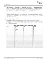
Table 1. ADS522xEVM Connectors
Connector ID Function Default Configuration
J1 SMA, Analog input of DUT through transformer Installed
J2 SMA, Analog input of DUT through OPA Installed
J3 SMA, Clock input of DUT through TTL translator Installed
J4 SMA, optional external clock input of Installed
SN74LVTH16374
J5 40-Pin Terminal Strip, EVM digital output data bus Installed
P1 3-pin Terminal block, OPA power supply Installed
P2 6-pin Terminal block, DUT power supply Installed
TP1 Optional connector for external reference voltage Installed
TP2 Optional connector for input common-mode voltage Installed
Table 2. ADS522xEVM Three-Pin Jumper
Jumper ID Function Default Configuration
JP1 Pin 2 is connected with MSB (pin 1 of ADS522x), Installed 1-2
pin 1 is GND, and pin 3 is +3.3V.
JP2 Pin 2 is connected with CE (pin 2 of ADS522x), Installed 1-2
pin 1 is GND, and pin 3 is +3.3V.
JP3 Pin 2 is connected with MSEL (pin 3 of ADS522x), Installed 1-2
pin 1 is GND and pin 3 is +3.3V.
JP4 Pin 2 is connected with STPD (pin 4 of ADS522x), Installed 1-2
pin 1 is GND and pin 3 is +3.3V.
JP5 Pin 2 is connected with QPD (pin 5 of ADS522x), Installed 1-2
pin 1 is GND and pin 3 is +3.3V.
JP6 Pin 2 is connected with RSEL (pin 31 of ADS522x), Installed 1-2
pin 1 is GND and pin 3 is +3.3V.
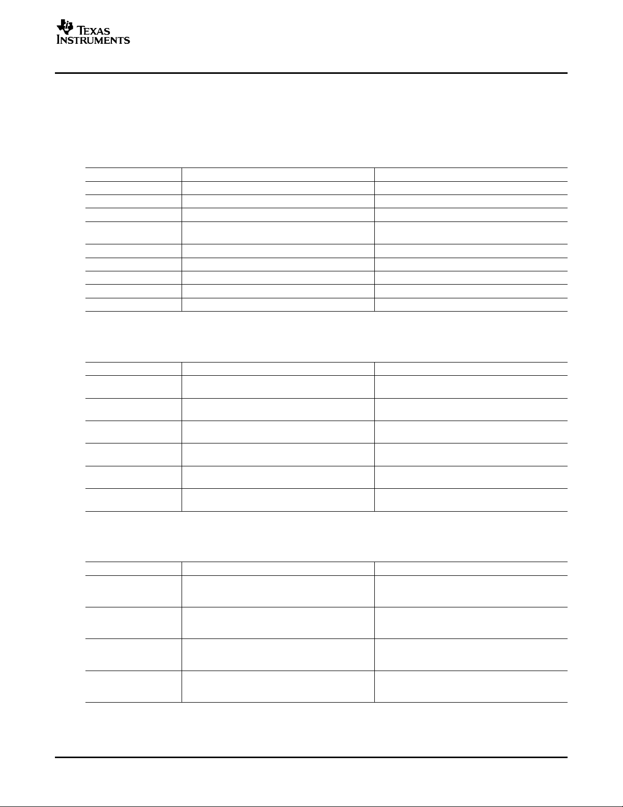
Table 3. 0 Ω Resistor Connection (Jumper) for Three Analog Input Options
Option ID Configuration Default
Option 1 – Differential R11 and R16 are on. R12 and R15 are off. R22, Yes
input through R54, R55, R69 are on. R8, R14, R7, R56 are off.
transformer C13, C54 and C55 are off. C39 is on.
Option 2 - Single-ended R11 and R16 are on. R12 and R15 are off. R7, R8, No
input through R56 and R57 are on. R14, R22, R54, R55 and R69
transformer are off. C13, C54, C55 are on. C39 is off.
Option 3 - Differential in- R12 and R15 are on. R11 and R16 are off. R13 No
put through OPA and R14 are on. R56, R57, R7 and R8 are off.
C13 is off, and C39 is on.
R* are not installed in R12, R15, R21, R19, R36, R61, R60, R52, R58, No
the default case R23, R18 and R70 are not installed for default
mode.
SBAU094 – June 2005 ADS522xEVM User's Guide 3
器件 Datasheet 文档搜索
AiEMA 数据库涵盖高达 72,405,303 个元件的数据手册,每天更新 5,000 多个 PDF 文件
