Datasheet 搜索 > 微控制器 > NXP(恩智浦) > LPC1788FET208,551 数据手册 > LPC1788FET208,551 产品设计参考手册 6/1110 页
¥ 124.891
LPC1788FET208,551 产品设计参考手册 - NXP(恩智浦)
制造商:
NXP(恩智浦)
分类:
微控制器
封装:
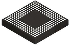
TFBGA-208
描述:
ARM Cortex-M3 Microcontrollers, NXP基于 NXP ARM Cortex-M3 的微控制器,适用于嵌入式应用,具有高集成水平并提供系统增强功能,例如低功耗、增强调试功能和更高级别的块集成支持。Cortex-M3 核可最高以 150 MHz 运行 高达 512KB 的闪存和高达 64KB 的片上 SRAM 低功耗,用于 LPC13xx 设备时低至 200μA/MHz 新唤醒中断控制器 (WIC)、套放向量中断控制器 (NVIC) 和存储器保护装置 配有先进的外围设备,如以太网、USB 主机/OTG/设备、CAN、IS、快速模式 Plus (Fm+) IC、12 位 ADC、电机控制 PWM、正交编码器接口和其他。 ### ARM Cortex 微控制器,NXP
Pictures:
3D模型
符号图
焊盘图
引脚图
产品图
页面导航:
引脚图在P22P23P90P91P92P93P94P95P96P97P98P99Hot
原理图在P739
型号编码规则在P9
封装信息在P134
功能描述在P39P334P437P445P771P834P865
应用领域在P8P134P631P658P659P660P661P662P663P701P799P808
型号编号列表在P214
导航目录
LPC1788FET208,551数据手册
Page:
of 1110 Go
若手册格式错乱,请下载阅览PDF原文件

UM10470 All information provided in this document is subject to legal disclaimers. © NXP Semiconductors N.V. 2016. All rights reserved.
User manual Rev. 4.0 — 19 December 2016 6 of 1110
NXP Semiconductors
UM10470
Chapter 1: Introductory information
– Five UARTs with fractional baud rate generation, internal FIFOs, IrDA, DMA
support, and RS-485/EIA-485 support. UART1 also has a full set of modem
handshaking signals. UART4 includes a synchronous mode and a smart card
mode supporting ISO 7816-3. Devices in the 144-pin package provide 4 UARTs.
– Three SSP controllers with FIFO and multi-protocol capabilities. The SSP
interfaces can be used with the GPDMA controller.
– Three enhanced I
2
C-bus interfaces, one with an open-drain output supporting the
full I
2
C specification and Fast mode Plus with data rates of 1Mbit/s, two with
standard port pins. Enhancements include multiple address recognition and
monitor mode.
– Two-channel CAN controller.
– I
2
S (Inter-IC Sound) interface for digital audio input or output, with fractional rate
control. The I
2
S interface can be used with the GPDMA. The I
2
S interface supports
3-wire data transmit and receive or 4-wire combined transmit and receive
connections, as well as master clock output.
– SPIFI (SPI Flash Interface), available on LPC1773 only. This interface uses an SPI
bus superset with 4 data lines to access off-chip Quad SPI Flash memory at a
much higher rate than is possible using standard SPI or SSP interfaces. The SPIFI
function allows memory mapping the contents of the off-chip SPI Flash memory
such that it can be executed as if it were on-chip code memory. Supports SPI
memories with 1 or 4 data lines.
• Other peripherals:
– SD card interface that also supports MMC cards.
– General Purpose I/O (GPIO) pins with configurable pull-up/down resistors, open
drain mode, and repeater mode. All GPIOs are located on an AHB bus for fast
access, and support Cortex-M3 bit-banding. GPIOs can be accessed by the
General Purpose DMA Controller. Any pin of ports 0 and 2 can be used to generate
an interrupt. There are 165 GPIOs on 208-pin packages, 141 GPIOs on 180-pin
packages, and 109 GPIOs on 144-pin packages.
– 12-bit Analog-to-Digital Converter (ADC) with input multiplexing among eight pins,
conversion rates up to 400 kHz, and multiple result registers. The 12-bit ADC can
be used with the GPDMA controller.
– 10-bit Digital-to-Analog Converter (DAC) with dedicated conversion timer and DMA
support.
– Four general purpose timers/counters, with a total of eight capture inputs and ten
compare outputs. Each timer block has an external count input. Specific timer
events can be selected to generate DMA requests.
– One motor control PWM with support for three-phase motor control.
– Quadrature encoder interface that can monitor one external quadrature encoder.
– Two standard PWM/timer blocks with external count input option.
– Real-Time Clock (RTC) with a separate power domain. The RTC is clocked by a
dedicated RTC oscillator. The RTC block includes 20 bytes of battery-powered
backup registers, allowing system status to be stored when the rest of the chip is
powered off. Battery power can be supplied from a standard 3 V Lithium button
cell. The RTC will continue working when the battery voltage drops to as low as
2.1 V. An RTC interrupt can wake up the CPU from any reduced power mode.
器件 Datasheet 文档搜索
AiEMA 数据库涵盖高达 72,405,303 个元件的数据手册,每天更新 5,000 多个 PDF 文件

