Datasheet 搜索 > 微控制器 > Microchip(微芯) > PIC16F87-I/SO 数据手册 > PIC16F87-I/SO 用户编程技术手册 1/24 页
 器件3D模型
¥ 27.326
PIC16F87-I/SO 用户编程技术手册 - Microchip(微芯)
制造商:
Microchip(微芯)
分类:
微控制器
封装:
SOIC-18
描述:
MICROCHIP PIC16F87-I/SO 微控制器, 8位, 闪存, PIC16F, 20 MHz, 7 KB, 368 Byte, 18 引脚, SOIC
Pictures:
3D模型
符号图
焊盘图
引脚图
产品图
页面导航:
引脚图在P4Hot
电气规格在P18

导航目录
PIC16F87-I/SO数据手册
Page:
of 24 Go
若手册格式错乱,请下载阅览PDF原文件
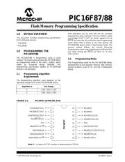
2010 Microchip Technology Inc. DS39607C-page 1
PIC16F87/88
1.0 DEVICE OVERVIEW
This document includes programming specifications
for the following devices:
•PIC16F87
•PIC16F88
2.0 PROGRAMMING THE
PIC16F87/88
The PIC16F87/88 is programmed using a serial
method. The Serial mode will allow the PIC16F87/88 to
be programmed while in the user’s system, which
allows for increased design flexibility. This
programming specification applies to PIC16F87/88
devices in all packages.
2.1 Programming Algorithm
Requirements
The programming algorithm used depends on the
operating voltage (V
DD) of the PIC16F87/88 device.
Both algorithms can be used with the two available
programming entry methods. The first method, called
Low-Voltage ICSP
TM
(LVP for short), applies VDD to
MCLR
and uses the I/O pin RB3 to enter Programming
mode. When RB3 is driven to V
DD from ground, the
PIC16F87/88 device enters Programming mode. The
second method follows the normal Microchip
Programming mode entry of holding pins RB6 and RB7
low, while raising the MCLR pin from VIL to VIHH
(13V ± 0.5V).
2.2 Programming Mode
The Programming mode for the PIC16F87/88 allows
programming of user program memory, data memory,
special locations used for ID, and the Configuration
Words.
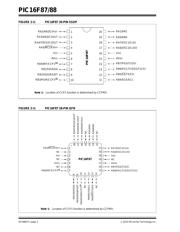
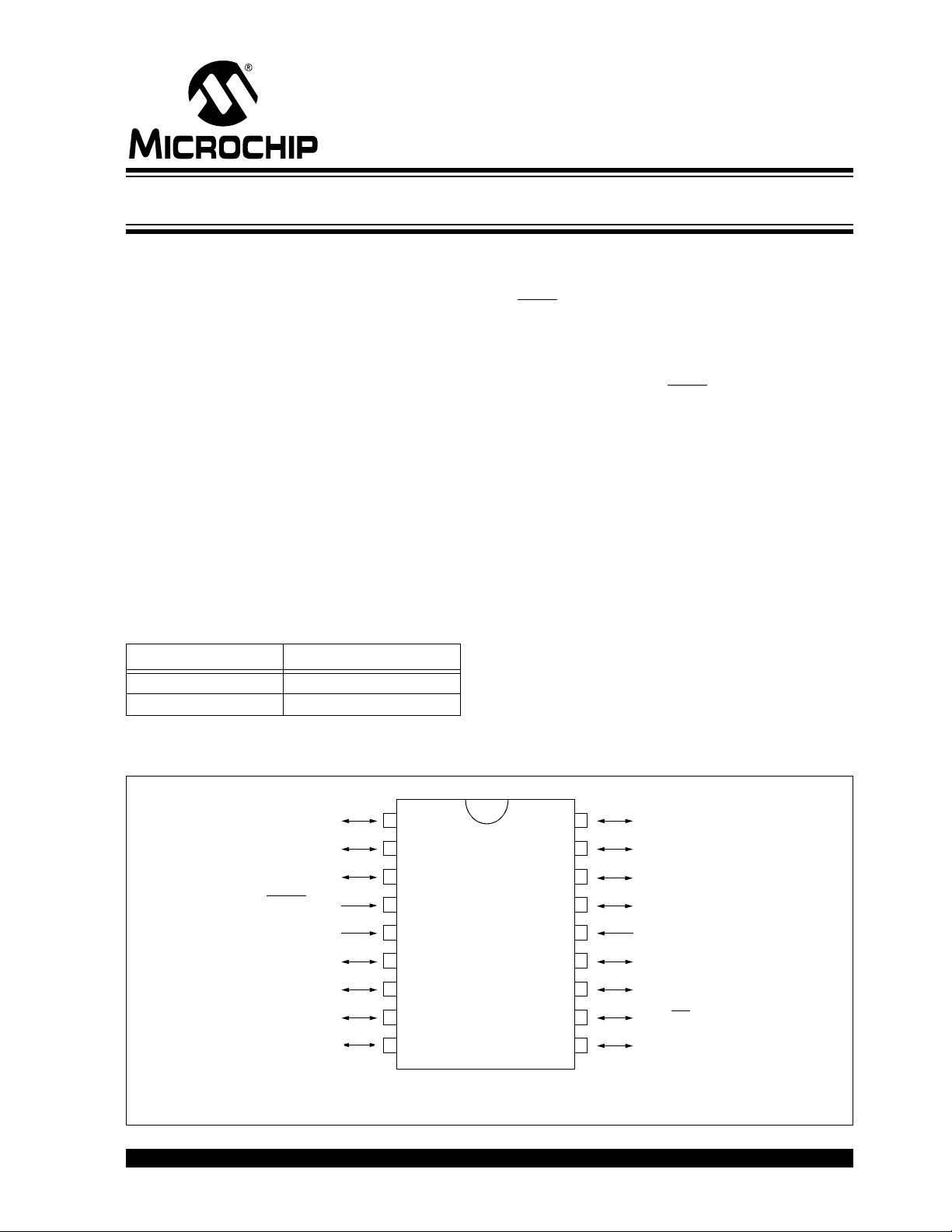
FIGURE 2-1: PIC16F87 18-PIN DIP, SOIC
Algorithm # VDD Range
12.0V V
DD <5.5V
24.5V VDD 5.5V
RA1/AN1
RA0/AN0
RA7/OSC1/CLKI
RA6/OSC2/CLKO
V
DD
RB7/PGD/T1OSI
RB6/PGC/T1OSO/T1CKI
RB5/SS
/TX/CK
RB4/SCK/SCL
RA2/AN2/CVREF
RA3/AN3/C1OUT
RA4/T0CKI/C2OUT
RA5/MCLR
/VPP
VSS
RB0/INT/CCP1
(1)
RB1/SDI/SDA
RB2/SDO/RX/DT
RB3/PGM/CCP1
(1)
1
2
3
4
5
6
7
8
9
18
17
16
15
14
13
12
11
10
PIC16F87
Note 1: Location of CCP1 function is determined by CCPMX.
Flash Memory Programming Specification
器件 Datasheet 文档搜索
AiEMA 数据库涵盖高达 72,405,303 个元件的数据手册,每天更新 5,000 多个 PDF 文件
