Datasheet 搜索 > 微控制器 > Microchip(微芯) > PIC18F14K22-E/ML 数据手册 > PIC18F14K22-E/ML 用户编程技术手册 1/36 页
 器件3D模型
¥ 17.481
PIC18F14K22-E/ML 用户编程技术手册 - Microchip(微芯)
制造商:
Microchip(微芯)
分类:
微控制器
封装:
QFN-20
描述:
20引脚闪存单片机采用nanoWatt XLP技术 20-Pin Flash Microcontrollers with nanoWatt XLP Technology
Pictures:
3D模型
符号图
焊盘图
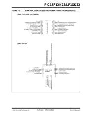
引脚图
产品图
页面导航:
引脚图在P2Hot
电气规格在P33P34
导航目录
PIC18F14K22-E/ML数据手册
Page:
of 36 Go
若手册格式错乱,请下载阅览PDF原文件

© 2009 Microchip Technology Inc. Advance Information DS41357B-page 1
PIC18F1XK22/LF1XK22
1.0 DEVICE OVERVIEW
This document includes the programming
specifications for the following devices:
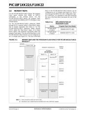
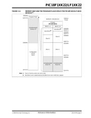
2.0 PROGRAMMING OVERVIEW
The PIC18F1XK22/LF1XK22 devices can be
programmed using either the high-voltage In-Circuit
Serial Programming™ (ICSP™) method or the low-
voltage ICSP method. Both methods can be done with
the device in the users’ system. The low-voltage ICSP
method is slightly different than the high-voltage
method and these differences are noted where
applicable. The PIC18F1XK22 devices operate from
1.8 to 5.5 volts and the PIC18LF1XK22 devices
operate from 1.8 to 3.6 volts. All other aspects of the
PIC18F1XK22 with regards to the PIC18LF1XK22
devices are identical.
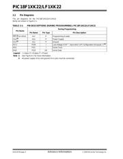
2.1 Hardware Requirements
In High-Voltage ICSP mode, the PIC18F1XK22/
LF1XK22 devices require two programmable power
supplies: one for V
DD and one for MCLR/VPP/RA3.
Both supplies should have a minimum resolution of
0.25V. Refer to Section 8.0 “AC/DC Characteristics
Timing Requirements for Program/Verify Test
Mode” for additional hardware parameters.
2.1.1 LOW-VOLTAGE ICSP
PROGRAMMING
In Low-Voltage ICSP mode, the PIC18F1XK22/
LF1XK22 devices can be programmed using a single
V
DD source in the operating range. The MCLR/VPP/
RA3 does not have to be brought to a different voltage,
but can instead be left at the normal operating voltage.
Refer to Section 8.0 “AC/DC Characteristics Timing
Requirements for Program/Verify Test Mode” for
additional hardware parameters.
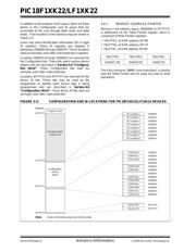
2.1.1.1 Single-Supply ICSP Programming
The LVP bit in Configuration register, CONFIG4L,
enables single-supply (low-voltage) ICSP
programming. The LVP bit defaults to a ‘1’ (enabled)
from the factory.
If Single-Supply Programming mode is not used, the
LVP bit can be programmed to a ‘0’ and RC3/PGM
becomes a digital I/O pin. However, the LVP bit may
only be programmed by entering the High-Voltage
ICSP mode, where MCLR
/VPP/RA3 is raised to VIHH.
Once the LVP bit is programmed to a ‘0’, only the
High-Voltage ICSP mode is available and only the
High-Voltage ICSP mode can be used to program the
device.
• PIC18F13K22 • PIC18LF13K22
• PIC18F14K22 • PIC18LF14K22
Note 1: The High-Voltage ICSP mode is always
available, regardless of the state of the
LVP bit, by applying V
IHH to the MCLR/
V
PP/RA3 pin.
2: While in Low-Voltage ICSP mode, the
RC3 pin can no longer be used as a
general I/O.
Flash Memory Programming Specification
器件 Datasheet 文档搜索
AiEMA 数据库涵盖高达 72,405,303 个元件的数据手册,每天更新 5,000 多个 PDF 文件
