Datasheet 搜索 > EEPROM芯片 > Microchip(微芯) > 24LC024/P 数据手册 > 24LC024/P 开发手册 1/14 页
 器件3D模型
¥ 3.219
24LC024/P 开发手册 - Microchip(微芯)
制造商:
Microchip(微芯)
分类:
EEPROM芯片
封装:
PDIP-8
描述:
24AA32A 系列 32 Kb I2C (4 K X 8) 1.7 V 串行 EEPROM SMT - SOIC-8
Pictures:
3D模型
符号图
焊盘图
引脚图
产品图
页面导航:
功能描述在P2
导航目录
24LC024/P数据手册
Page:
of 14 Go
若手册格式错乱,请下载阅览PDF原文件
© 2008 Microchip Technology Inc. DS01195B-page 1
AN1195
INTRODUCTION
The 24XXX series serial EEPROMs from Microchip
Technology support a bidirectional, 2-wire bus and data
transmission protocol. The bus is controlled by the
microcontroller (master), which generates the Serial
Clock (SCL), controls the bus access and generates
the Start and Stop conditions, while the 24XXX serial
EEPROM works as slave. The 24XXX serial
EEPROMs are I
2
C™
compatible and have maximum
clock frequencies ranging from 100 kHz to 1 MHz.
The main features of the 24XXX serial EEPROMs are:
• 2-wire serial interface bus, I
2
C compatible
• EEPROM densities from 128 bits to 512 Kbits
• Bus speed from 100 kHz to 1 MHz
• Voltage range from 1.7V to 5.5V
• Low power operation
• Temperature range from -40°C to +125°C
• Over 1,000,000 erase/write cycles
• Up to 8 devices may be connected to same bus
This application note is part of a series that provide
source code to help the user implement the protocol
with minimal effort.
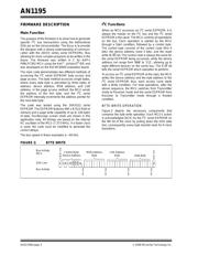
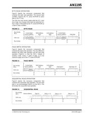
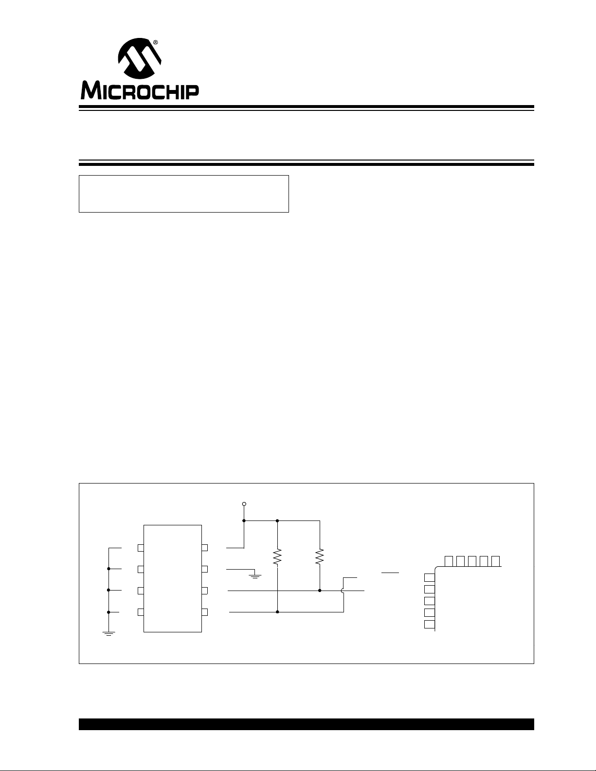
Figure 1 is the hardware schematic depicting the
interface between the Microchip 24XXX series of I
2
C
serial EEPROMs and NXP’s P89LPC952 8051-based
MCU. The schematic shows the connections
necessary between the MCU and the serial EEPROM
as tested, as well as the required pull-up resistors on
the clock line (SCL) and data line (SDA). Not illustrated
in this application note are the write-protect feature and
the cascading of multiple devices; thus, the WP pin and
address pins A0, A1 and A2 are tied to V
SS (ground).
The test software was written assuming these
connections.
FIGURE 1: CIRCUIT FOR P89LPC952 MCU AND 24XXX SERIES I
2
C SERIAL EEPROM
Author: Alexandru Valeanu
Microchip Technology Inc.
7
8
6
5
1
2
3
4
A0
A1
A2
Vss
Vcc
WP
SCL
SDA
P1.2
T0
/SCL
P1.3 INT0
/SDA
Vcc
7
8
P89LPC952
24XX512
Note: A decoupling capacitor (typically 0.1 µF) should be used to filter noise on VCC.
4.7 k
Ω
Using C to Interface 8051 MCUs
with I
2
C™ Serial EEPROMs
器件 Datasheet 文档搜索
AiEMA 数据库涵盖高达 72,405,303 个元件的数据手册,每天更新 5,000 多个 PDF 文件
