Datasheet 搜索 > RF射频器件 > ADI(亚德诺) > AD8339ACPZ 数据手册 > AD8339ACPZ 开发手册 1/12 页
 器件3D模型
¥ 31.703
AD8339ACPZ 开发手册 - ADI(亚德诺)
制造商:
ADI(亚德诺)
分类:
RF射频器件
封装:
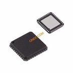
LFCSP-40
描述:
ANALOG DEVICES AD8339ACPZ 芯片, 正交解调器
Pictures:
3D模型
符号图
焊盘图
引脚图
产品图
AD8339ACPZ数据手册
Page:
of 12 Go
若手册格式错乱,请下载阅览PDF原文件
AN-922
APPLICATION NOTE
One Technology Way • P. O. Box 9106 • Norwood, MA 02062-9106, U.S.A. • Te l: 781.329.4700 • Fax: 781.461.3113 • www.analog.com
Digital Pulse-Shaping Filter Basics
by Ken Gentile
Rev. 0 | Page 1 of 12
INTRODUCTION
Data transmission systems that must operate in a bandwidth-
limited environment must contend with the fact that constraining
the bandwidth of the transmitted signal necessarily increases
the likelihood of a decoding error at the receiver. Bandwidth
limited systems often employ pulse-shaping techniques that
allow for bandwidth containment while minimizing the
likelihood of errors at the receiver.
Before digital filters were available, pulse shaping was accom-
plished with analog filters. Unfortunately, the response of an
analog filter is affected by variations in component values due
to specified tolerance ranges, temperature, and aging. The
response of a digital filter, by contrast, is solely dependent on
the filter coefficients, which are invariant to both temperature
and aging. Therefore, digital pulse-shaping filters have become
an integral part of many digital data transmission systems. This
application note describes the fundamentals of pulse shaping
and the tradeoffs associated with the design of digital pulse-
shaping filters.
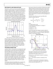
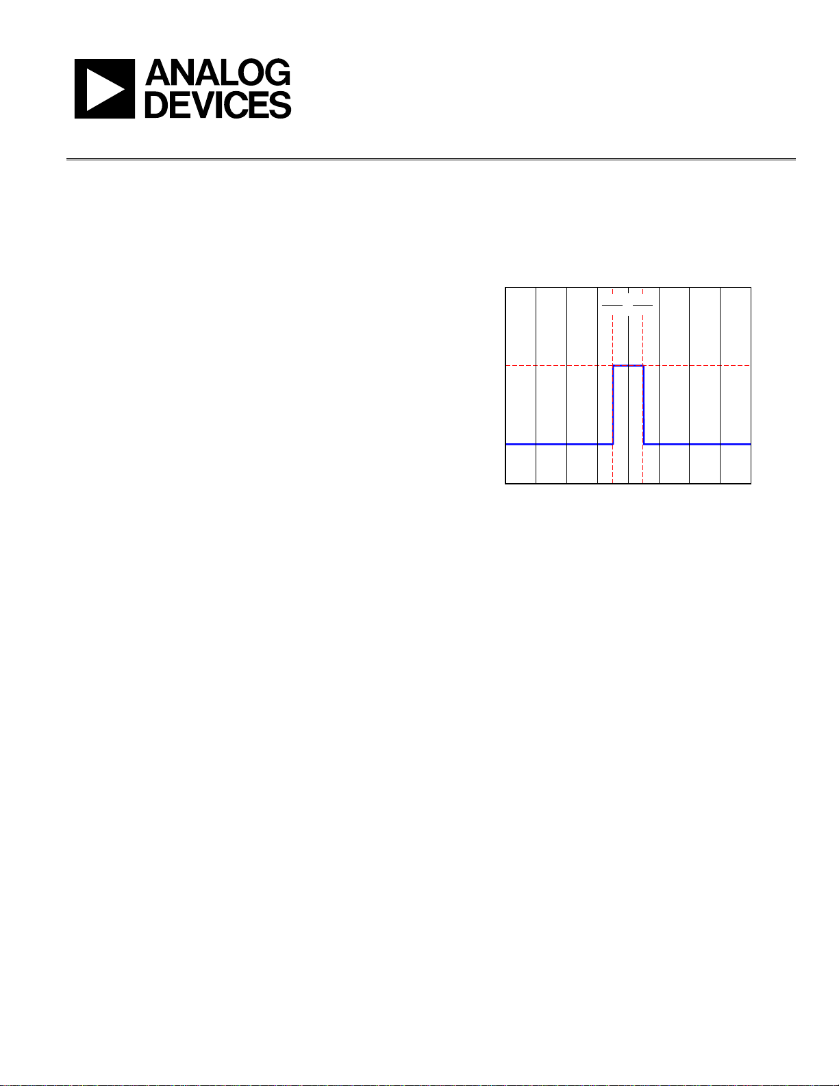
THE RECTANGULAR PULSE
The most basic information unit in a digital transmission
scheme is a rectangular pulse. It has a defined amplitude,
A, and defined duration, T. Such a pulse is shown in
Figure 1,
where A = 1, T = T
o
, with the pulse centered about the time
origin at t = 0. Typically, a sequence of such pulses (each
delayed by T seconds relative to the previous one) constitutes
the transmission of information. The information, in this
case, is encoded in the amplitude of the pulse. The simplest
case is when a binary 0 is encoded as the absence of a pulse
(A = 0) and a binary 1 is encoded as the presence of a pulse
(A = constant). Since each pulse spans the period T, the maxi-
mum pulse rate is 1/T pulses per second, which leads to a data
transmission rate of 1/T
bits per second.
In more sophisticated data transmission schemes, the pulse
amplitude can take on both positive and negative values with
multiple discrete amplitudes used to encode more than one bit
into the pulse. For example, four levels can be used to encode
two bits in which each level is uniquely associated with one of
the four possible bit patterns. In some cases, multiple pulses are
transmitted simultaneously, which allows even more bits to be
encoded (see the Multibit Symbol Encoding section).
–T
O
2
T
O
2
2
1
0
–4–3–2–101234
AMPLITUDE
TIME (IN UNITS OF T
O
)
RECTANGULAR PULSE (TIME DOMAIN)
A
06897-001
Figure 1. A Single Rectangular Pulse (T = T
O
, A = 1)
In sophisticated transmission systems, multiple amplitudes
and/or multiple simultaneous pulses transmit a single unit of
data. As such, each single unit of data can represent more than
one bit. The group of bits that a single unit of data represents is
referred to as a symbol. The trivial case, of course, is the single
bipolar pulse of
Figure 1 where each unit of data is a single bit
(symbol and bit are synonymous in this case).
The pulses used to transmit symbols occupy a fixed time inter-
val, T (as in
Figure 1). Thus, the pulse rate is 1/T pulses per
second, which leads to a symbol rate of 1/T symbols per second.
The unit, symbols per second, is often referred to as baud. The
data transmission rate in bits per second is the baud rate
multiplied by the number of bits represented by each symbol.
For example, if a symbol represents four bits, then the bit rate is
four times the symbol rate. This means that a lower transmission
rate can be used to transmit symbols as opposed to directly
transmitting bits, which is the primary reason that the more
sophisticated data transmission systems encode groups of bits
into symbols. The remainder of this application note focuses on
a single bipolar pulse for transmitting one bit at a time. That is, a
logical 1 is represented by the presence of a pulse of unit
amplitude and a logical 0 by the absence of a pulse (that is, zero
amplitude). The concepts discussed in this application note,
however, extend directly to the more sophisticated encoding
schemes.
器件 Datasheet 文档搜索
AiEMA 数据库涵盖高达 72,405,303 个元件的数据手册,每天更新 5,000 多个 PDF 文件
