Web Analytics
Datasheet 搜索 > MOS管 > Infineon(英飞凌) > IRF40H210 数据手册 > IRF40H210 开发手册 5/37 页
IRF40H210
器件3D模型
7.652
IRF40H210数据手册
Page:
of 37 Go
若手册格式错乱,请下载阅览PDF原文件
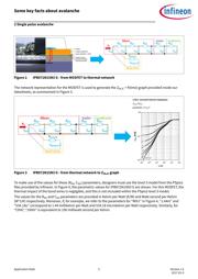
Figure 2 IPB072N15N3 G - from MOSFET to thermal network
The network representation for the MOSFET is used to generate the Z
thJC
= f(time) graph provided inside our
datasheets, as summarized in Figure 3.
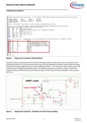
Figure 3 IPB072N15N3 G - from thermal network to Z
thJC
graph
To make use of the values for these (R
thi
, C
thi
) parameters, designers must use the level 3 model from the PSpice
files provided by Infineon. In Figure 4, the parametric values for IPB072N15N3 G are shown. For this MOSFET, the
thermal impact of the bond wires is negligible, and this is not included within the PSpice level 3 model.
The values for the R
thi
and C
thi
parameters are provided in Kelvin per Watt (K/W) and Watt-second per Kelvin
(W*s/K) respectively. Moreover, if, for example, we refer to the parameters for “Rth1” in Figure 4, “1.44m” and
“534.18u” correspond to 1.44 millikelvin per Watt and 534.18 microkelvin per Watt respectively. Similarly, for
“Cth6”, “190m” is equivalent to 190 milliwatt-second per Kelvin.
Some key facts about avalanche
2 Single pulse avalanche
Application Note 5 Version 1.0
2017-01-9

IRF40H210 数据手册

Infineon(英飞凌)
11 页 / 0.55 MByte
Infineon(英飞凌)
270 页 / 11.59 MByte
Infineon(英飞凌)
30 页 / 0.64 MByte
Infineon(英飞凌)
2 页 / 0.17 MByte
Infineon(英飞凌)
37 页 / 2.01 MByte

IRF40 数据手册

Infineon(英飞凌)
单 P沟道 -12 V 1.3 W 10 nC 功率Mosfet 表面贴装 - MICRO-3
Infineon(英飞凌)
晶体管, MOSFET, StrongIRFET™, N沟道, 90 A, 40 V, 0.0042 ohm, 10 V, 3 V
Infineon(英飞凌)
IRF40H210 编带
Infineon(英飞凌)
场效应管(MOSFET) IRF40DM229 DirectFET
International Rectifier(国际整流器)
Infineon(英飞凌)
N沟道 40V 360A
PCN
Withstand voltage (1500 V ac, 1 minute) | ±(1%+0.05 Ω) ---|--- Overload (rated power x 5: 5 sec) | ±(1%+0.05 Ω) Insulation resistance (500 V dc) | At least 20 MΩ Temperature coefficient of resistance (+25 to +155°C) | ±260 ppm/°C Sudden temperature change (heat impact) (-55°C to +155°C: 5 cycles) | ±(1%+0.05 Ω) Type | L1 ±1 (mm) | L2 ±0.3 (mm) | W1 ±0.3 (mm) | W2 ±0.3 (mm) | Lead wire 1.25 mm2 | Lead wire 2 mm2 ---|---|---|---|---|---|--- IRF100NC | 90 | 70 | 80 | 70 | 1 Ω or higher | — IRF200NC | 150 | 130 | 80 | 70 | 4.1 Ω or higher | 1 to 4 Ω IRF300NC | 210 | 190 | 80 | 70 | 6.1 Ω or higher | 1 to 6 Ω IRF400NC | 270 | 250 | 80 | 70 | 8.1 Ω or higher | 1 to 8 Ω IRF500NC | 330 | 310 | 80 | 70 | 10.1 Ω or higher | 1 to 10 Ω ### 铝封装线绕 - 5 到 600W
器件 Datasheet 文档搜索
器件加载中...
AiEMA 数据库涵盖高达 72,405,303 个元件的数据手册,每天更新 5,000 多个 PDF 文件