Datasheet 搜索 > Vishay BC Components(威世) > A104K15X7RF5TAAV 数据手册 > A104K15X7RF5TAAV 数据手册 1/9 页


¥ 1.14
A104K15X7RF5TAAV 数据手册 - Vishay BC Components(威世)
制造商:
Vishay BC Components(威世)
Pictures:
3D模型
符号图
焊盘图
引脚图
产品图
A104K15X7RF5TAAV数据手册
Page:
of 9 Go
若手册格式错乱,请下载阅览PDF原文件
A...V Series
www.vishay.com
Vishay BCcomponents
Revision: 26-Feb-16
1
Document Number: 45212
For technical questions, contact: cmll@vishay.com
THIS DOCUMENT IS SUBJECT TO CHANGE WITHOUT NOTICE. THE PRODUCTS DESCRIBED HEREIN AND THIS DOCUMENT
ARE SUBJECT TO SPECIFIC DISCLAIMERS, SET FORTH AT www.vishay.com/doc?91000
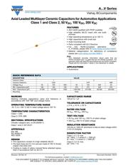
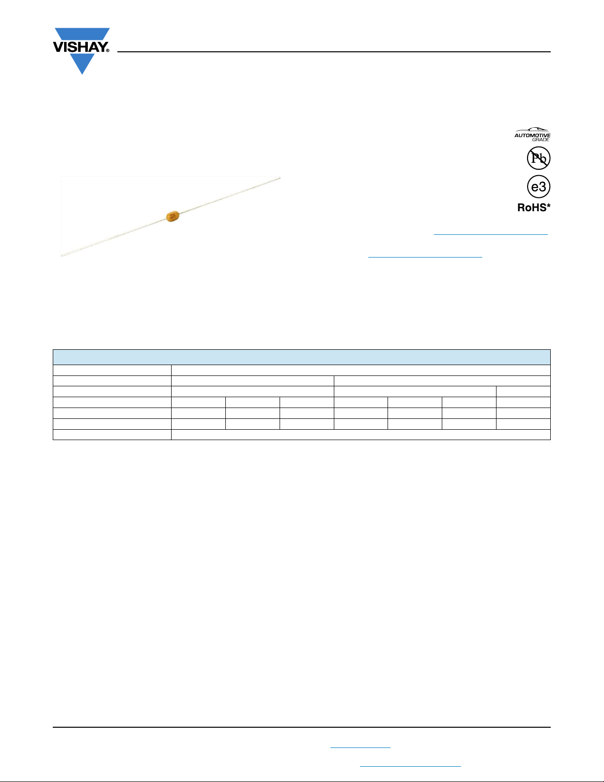
Axial Leaded Multilayer Ceramic Capacitors for Automotive Applications
Class 1 and Class 2, 50 V
DC
, 100 V
DC
, 200 V
DC
FEATURES
• AEC-Q200 qualified with PPAP available
• High reliability MLCC insert with wet build
process
• High operating temperature up to 160 °C
• High capacitance with small size
• Axial mounting style
• Parts compliant with ELV Directive
• For fully RoHS-compliant alternative
A...R Series, please refer to www.vishay.com/doc?45231
• Material categorization: for definitions of compliance
please see www.vishay.com/doc?99912
Note
*
This datasheet provides information about parts that are
RoHS-compliant and / or parts that are non-RoHS-compliant. For
example, parts with lead (Pb) terminations are not RoHS-compliant.
Please see the information / tables in this datasheet for details.
APPLICATIONS
• Automotive
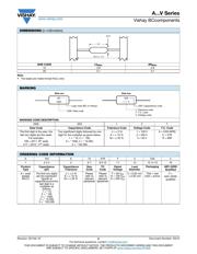
MARKING
Marking indicates capacitance value and tolerance in
accordance with “EIA 198” and voltage marks.
OPERATING TEMPERATURE RANGE
-55 °C to +160 °C (50 % rated voltage above 150 °C)
TEMPERATURE CHARACTERISTICS
Class 1: C0G
Class 2: X7R, X8R
SECTIONAL SPECIFICATIONS
Climatic category (acc. to EN 60058-1)
Class 1 and 2: 55/125/21
APPROVALS
EIA 198
IEC 60384-9
AEC-Q200
DESIGN
• The capacitors consist of a high reliability MLCC
• The lead wires are 0.5 mm and are made of 100 % tinned
copper clad steel wire
• Coating is made of yellow colored flame retardant epoxy
resin in accordance with UL 94 V-0
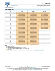
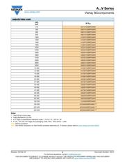
CAPACITANCE RANGE
100 pF to 1 μF
TOLERANCE ON CAPACITANCE
± 5 %, ± 10 %, ± 20 %
RATED VOLTAGE
50 V
DC
, 100 V
DC
, 200 V
DC
TEST VOLTAGE
• 50 V
DC
and 100 V
DC
: 250 % of rated voltage
• 200 V
DC
: 200 % of rated voltage
INSULATION RESISTANCE
100 G or 1000 F whichever is less at rated voltage within
2 min of charging.
DISSIPATION FACTOR
Class 1: 0.1 % max.
(at 1 MHz, 1 V where C 1000 pF;
at 1 kHz; 1 V where C > 1000 pF)
Class 2: 2.5 % max.
(at 1 kHz, 1 V)
Available
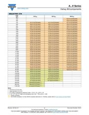
QUICK REFERENCE DATA
DESCRIPTION VALUE
Ceramic Class 1 2
Ceramic Dielectric C0G X7R X8R
Voltage (V
DC
) 50 100 200 50 100 200 50
Min. Capacitance (pF) 100 100 100 470 470 330 470
Max. Capacitance (pF) 10 000 10 000 1000 1 000 000 470 000 68 000 330 000
Mounting Axial
器件 Datasheet 文档搜索
AiEMA 数据库涵盖高达 72,405,303 个元件的数据手册,每天更新 5,000 多个 PDF 文件
